MiraOne Radio Module
MiraOne module
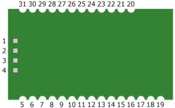
Pinout
Module seen from the top

| Pin | Name | Pin type | Description |
|---|---|---|---|
| 1 | NC | Do not connect | |
| 2 | NC | Do not connect | |
| 3 | NC | Do not connect | |
| 4 | NC | Do not connect | |
| 5 | PC7 | Digital I/O | GPIO0 / UART1 RXD (command UART) |
| 6 | PC6 | Digital I/O | GPIO1 / UART1 TXD (command UART) |
| 7 | PC5 | Digital I/O | GPIO2 / I2C SDA |
| 8 | PC4 | Digital I/O | GPIO3 / I2C SCA |
| 9 | PC3 | Digital I/O | GPIO41 |
| 10 | PC2 | Digital I/O | GPIO52 |
| 11 | PC1 | Digital I/O | GPIO62 |
| 12 | PA0 | Digital I/O / Analog I | GPIO7 / UART0 RXD (debug UART) / ADC0 |
| 13 | PA1 | Digital I/O / Analog I | GPIO8 / UART0 TXD (debug UART) / ADC1 |
| 14 | PA2 | Digital I/O | SPI CLK3 |
| 15 | PA3 | Digital I/O | GPIO94 |
| 16 | PA4 | Digital I/O | SPI MOSI3 |
| 17 | PA5 | Digital I/O | SPI MISO3 |
| 18 | PA6 | Digital I/O / Analog I | GPIO9 / ADC2 |
| 19 | PA7 | Digital I/O / Analog I | GPIO10 / ADC3 |
| 20 | GND | Power | Supply ground |
| 21 | GND | Power | Supply ground |
| 22 | PB5 | Digital I/O | GPIO11 / PWM1 |
| 23 | PB4 | Digital I/O | GPIO12 / PWM2 |
| 24 | PB3 | Digital I/O | GPIO13 / GPT A Trig |
| 25 | PB2 | Digital I/O | GPIO14 / Wake-up |
| 26 | PB1 | Digital I/O | GPIO15 |
| 27 | nRESET | Digital input | Device reset |
| 28 | USB_N | USB I/O | USB data negative (D-) |
| 29 | USB_P | USB I/O | USB data negative (D+) |
| 30 | GND | Power | Supply ground |
| 31 | VCC | Power | Power supply, 2.3-3.6 VDC |
1 High current pin, 20 mA sink/source capability. This pin is used as commissioning LED in Mira Commissioning Application.
2 High current pin, 20 mA sink/source capability.
3 SPI signals may not be used as GPIOs, SPI is used internally on the Mira module.
4 This pin must be high at power-up. If this pin is used, care must be taken to make sure this pin is high during power-up.
Electrical
Operating conditions
| Parameter | Symbol | Minimum | Maximum | Unit |
|---|---|---|---|---|
| Operating supply voltage | VCC | 2.3 | 3.6 | V |
| Operating ambient temp. | TA | -40 | 80 | °C |
Absolute maximum ratings
| Parameter | Symbol | Minimum | Maximum | Unit |
|---|---|---|---|---|
| Supply voltage | VCC | -0.3 | 3.6 | V |
| Peak current | IMAX | 250mA | mA | |
| Voltage on any digital pin | VIO | -0.3 | VCC+0.3 | V |
| Storage temperature | TSTG | -40 | 125 | °C |
| Input RF level | PIN | 10 | dBm | |
| Electrostatic discharge voltage (human body model), JEDEC STD 22, method A114 | VESD | 1 | kV |
Electrical characteristics
| Parameter | Symbol | Min | Typ | Max | Unit |
|---|---|---|---|---|---|
| Peak current consumption, continuous transmission @ 17dBm, no peripherals active | ITX_PEAK_17DBM | 120 | 150 | mA | |
| Peak current consumption, continuous transmission @ -2.7dBm, no peripherals active | ITX_PEAK_NEG2_7DBM | 60 | 80 | mA | |
| Peak current consumption, battery mode @ 2.5dBm, no peripherals active | ITX_PEAK_2_5DBM | 60 | 80 | mA | |
| Peak current consumption in RX mode, -50dBm input, no peripherals active | IRX | 40 | 60 | mA | |
| Peak current consumption in RX battery mode, -50dBm input, no peripherals active | IRX_BATT | 35 | 55 | mA | |
| Average current consumption, high power mode, 17dBm TX, no peripherals active | ITX_AVG | 45 | 50 | mA | |
| Average current consumption1, battery mode, 2.5dBm TX, no peripherals active | ITX_AVG_BATT | 35 | 40 | mA | |
| SPI current consumption | ISPI | 300 | μA | ||
| I2C current consumption | II2C | 100 | μA | ||
| UART current consumption | IUART | 700 | μA | ||
| USB current consumption | IUSB | 3.8 | mA | ||
| ADC current consumption when converting | IADC | 1.2 | mA | ||
| Flash erase current consumption | IFL_ER | 12 | mA | ||
| Flash write peak current | IFL_WR | 8 | mA | ||
| Deep sleep current consumption | ISLEEP | 10.5 | 11 | μA | |
| Logic 0 input voltage threshold | VLOW_TH | 0.5 | V | ||
| Logic 1 input voltage threshold | VHI_TH | 2.5 | V | ||
| Logic 0/1 input current | IIN_IO | -300 | 300 | nA |
1 One burst transmission including CSMA-CA, TX, MAC ACK, duration 4.9ms
ADC characteristics
TA = 25°C and VCC = 3.3V
| Parameter | Min | Typ | Max | Unit | ||
|---|---|---|---|---|---|---|
| Input voltage | 0 | VCC | V | |||
| Input resistance | 197 | kΩ | ||||
| ENOB | Effective number of bits | 10.2 | bits | |||
| Useful bandwidth | 20 | kHz | ||||
| THD | Total harmonic distortion | -75.2 | dB | |||
| Signal to non-harmonic ratio | 78.8 | dB | ||||
| CMRR | Common-mode rejection ratio | 84 | dB | |||
| Crosstalk | -84 | dB | ||||
| Offset | -3 | mV | ||||
| Gain error | 0.68 | % | ||||
| DNL | Differential nonlinearity | Mean | 0.05 | LSB | ||
| Maximum | 0.9 | LSB | ||||
| INL | Integral nonlinearity | Mean | 4.6 | LSB | ||
| Maximim | 13.3 | LSB | ||||
| SINAD (-THD+N) | Signal-to-noise-and-distortion | Single-ended | 66.6 | dB | ||
| Differential | 70.8 | dB | ||||
| Conversion time | 132 | μs | ||||
| Internal reference temperature coefficient | 0.4 | mV/10°C |
USB DC characteristics
TA = 25°C and VCC = 3.6V
| Parameter | Min | Typ | Max | Unit |
|---|---|---|---|---|
| USB pad voltage output, high, 4mA load | 3.4 | V | ||
| USB pad voltage output, low, 4mA load | 0.2 | V |
RF characteristics
Measured at 3.3V, 25°C. Limits apply over entire frequency range 2405-2480 MHz (channel 11-26).
| Parameter | Symbol | Min | Typ | Max | Unit |
|---|---|---|---|---|---|
| RF frequency range | 2405 | 2480 | MHz | ||
| Receiver sensitivity, PER = 1% | RXSENS | -101 | dBm | ||
| Receiver sensitivity battery mode, PER = 1% | RXSENS_BATT | -92 | dBm | ||
| Receiver saturation, PER = 1% | RXSAT | -5 | dBm | ||
| Transmitter max output power | POUT_MAX | 16.5 | 17 | 17.5 | dBm |
| Output return loss at U.FL connector | S22 | -10 | -5 | dB |
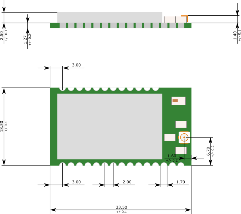
Dimensions

Compliance information
FCC information
FCC Information to User
This product does not contain any user serviceable components and is to be used with approved antennas only. Any product changes or modifications will invalidate all applicable regulatory certifications and approvals
FCC Guidelines for Human Exposure
This equipment complies with FCC radiation exposure limits set forth for an uncontrolled environment. This equipment should be installed and operated with minimum distance of 20 cm between the radiator and your body. This transmitter must not be co-located or operating in conjunction with any other antenna or transmitter.
FCC Declaration of Conformity
We LumenRadio AB, Svangatan 2B, 41668 Gothenburg, Sweden, declare under our sole responsibility that MiraOne comply with Part 15 of FCC Rules. Operation is subject to the following two conditions:
-
This device may not cause harmful interference, and
-
This device must accept any interference received, including interference that may cause undesired operation.
FCC Radio Frequency Interference Warnings & Instructions
This equipment has been tested and found to comply with the limits for a Class B digital device, pursuant to Part 15 of the FCC Rules. These limits are designed to provide reasonable protection against harmful interference in a residential installation. This equipment uses and can radiate radio frequency energy and, if not installed and used in accordance with the instructions, may cause harmful interference to radio communications. However, there is no guarantee that interference will not occur in a particular installation. If this equipment does cause harmful interference to radio or television reception, which can be determined by turning the equipment off and on, the user is encouraged to try to correct the interference by one or more of the following methods:
-
Reorient or relocate the receiving antenna
-
Increase the separation between the equipment and the receiver
-
Connect the equipment into an electrical outlet on a circuit different from that which the radio receiver is connected
-
Consult the dealer or an experienced radio/TV technician for help.
Modifications made to the product, unless expressly approved by LumenRadio AB, could void the user’s right to operate the equipment.
Industry Canada statement
This digital apparatus does not exceed the Class B limits for radio noise emissions from digital apparatus set out in the Radio Interference Regulations of the Canadian Department of Communications.
Le resent appareil numerique német pas de bruits radioélectriques dépassant les limites applicables aux appareils numériques de la classe B prescrites dans le Réglement sur le broullage radioélectrique édicté par le ministére des Communications du Canada.
CE
MiraOne comply with the Essential Requirements of RED (Radio Equipment Directive) of the European Union (2014/53/EU). MiraOne meet the ETSI EN 300 328 V1.8.1, ETSI EN 300 328 V1.9.1 and ETSI EN 300 328 V2.1.1 conformance standards for radio performance.
Compliance Marking
FCC & Industry Canada
The MiraOne modules are certified for FCC as a single-modular transmitter.
MiraOne modules are FCC certified radio module that carries a “Modular” grant. MiraOne radio modules complies to the “Intentional Radiator” portion (Part 15c) for FCC certification: Part 15.247 Transmitter tests.
An end product, incorporating a MiraOne module, does not require additional testing or authorization for the MiraOne transceiver. Host end products can use the FCC ID of the certified module as the FCC ID of the host end product. A label displaying the MiraOne module’s FCC ID must be affixed and visible on the host end product for approval.
FCC IDs are required for host end products with radio transmitters.
Other Compliances
For other local compliance regulations (CE, UL, CSA, SRRC, C-Tick, etc.) you are responsible as the product manufacturer to ensure all required compliance testing is completed. LumenRadio are happy to advise on compliance testing – please contact LumenRadio for details.