MiraOne Development Board
MiraOne Development Board
Connectors
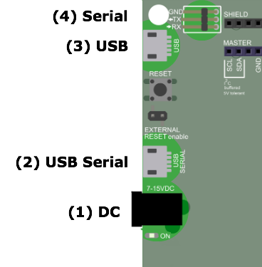
(1) DC
The DC circular plug can be used to power the board when no other power source is used. Note: The board can also be powered from any of the USB connectors, or from the shield interface.
(2) USB Serial
This connector is connected to a USB to serial adaptor used for flashing of the Mira module, and for debug prints from the application running on the Mira module.
(3) USB
This interface is a native USB interface connected directly to the USB pins of the Mira module.
(4) Serial
This connector allows for connecting a 3V3 level UART for connecting to anything external. One example is the USB to serial cable that is included in The Better World Kit.
Pinout
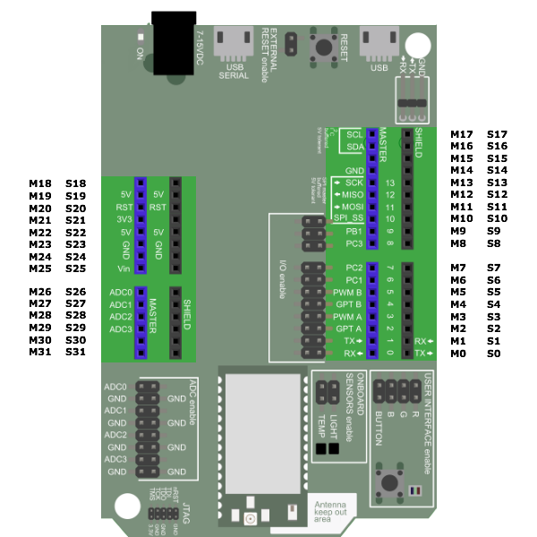
Shield
The shield pins are used when connecting to an Arduino compatible master board.
| Pin | Name | Pin type | Description |
|---|---|---|---|
| S0 | PC6 | Digital O | UART1 TXD (command UART) |
| S1 | PC71 | Digital I | UART1 RXD (command UART)1 |
| S2 | NC | ||
| S3 | NC | ||
| S4 | NC | ||
| S5 | NC | ||
| S6 | NC | ||
| S7 | NC | ||
| S8 | NC | ||
| S9 | NC | ||
| S10 | NC | ||
| S11 | NC | ||
| S12 | NC | ||
| S13 | NC | ||
| S14 | SHIELD_ENABLE | Digital I | Master board shall ground this pin to enable UART interface. |
| S15 | NC | ||
| S16 | NC | ||
| S17 | NC | ||
| S18 | NC | ||
| S19 | 5V | Power | 5V power |
| S20 | nRESET | Digital I | External reset input |
| S21 | NC | ||
| S22 | 5V | Power | 5V power |
| S23 | Gnd | Power | Supply ground |
| S24 | Gnd | Power | Supply ground |
| S25 | NC | ||
| S26 | NC | ||
| S27 | NC | ||
| S28 | NC | ||
| S29 | NC | ||
| S30 | NC | ||
| S31 | NC |
1 This pin is buffered to be 5V tolerant. SHIELD_ENABLE signal must be low to enable.
Master (stand-alone mode)
| Pin | Name | Pin type | Description |
|---|---|---|---|
| M0 | PC7 | GPIO0 / Digital I/O | UART1 RXD (command UART) |
| M1 | PC6 | GPIO1 / Digital I/O | UART1 TXD (command UART) |
| M2 | PB3 | Digital I/O | GPIO13 / GPT A Trig |
| M3 | PB5 | Digital I/O | GPIO11 / PWM1 |
| M4 | PB2 | Digital I/O | GPIO14 / Wake-up |
| M5 | PB4 | Digital I/O | GPIO12 / PWM2 |
| M6 | PC1 | Digital I/O | GPIO61 |
| M7 | PC2 | Digital I/O | GPIO51 |
| M8 | PC3 | Digital I/O | GPIO42 |
| M9 | PB1 | Digital I/O | GPIO15 |
| M10 | PA3 | Digital I/O | GPIO93 |
| M11 | MOSI | ||
| M12 | MISO | ||
| M13 | SCK | ||
| M14 | GND | Power | Supply ground |
| M15 | NC | ||
| M16 | SDA | I2C | I2C serial data5 |
| M17 | SCL | I2C | I2C serial clock5 |
| M18 | NC | ||
| M19 | 5V | Power | 5V power |
| M20 | nRESET | Digital I | External reset input |
| M21 | 3V3 | Power | 3V3 power |
| M22 | 5V | Power | 5V power |
| M23 | Gnd | Power | Supply ground |
| M24 | Gnd | Power | Supply ground |
| M25 | Vin | Power | External supply (7-15VDC) |
| M26 | PA0 | Digital I/O / Analog I | GPIO7 / UART0 RXD (debug UART) / ADC06 |
| M27 | PA1 | Digital I/O / Analog I | GPIO8 / UART0 TXD (debug UART) / ADC16 |
| M28 | PA6 | Digital I/O / Analog I | GPIO9 / ADC2 |
| M29 | PA7 | Digital I/O / Analog I | GPIO10 / ADC3 |
| M30 | SDA | I2C | I2C serial data5 |
| M31 | SCL | I2C | I2C serial clock5 |
1 High current pin, 20 mA sink/source capability.
2 High current pin, 20 mA sink/source capability. This pin is used as commissioning LED in Mira Commissioning Application.
3 This pin must be high at power-up. If this pin is used, care must be taken to make sure this pin is high during power-up.
4 SPI signals may not be used as GPIOs, SPI is used internally on the Mira module.
5 I2C signals are buffered and pulled-up on the Mira development board.
6 These pins are not available when USB Serial interface is used.
Sensors, actuators, etc
The development board is populated with two sensors (temperature and light sensors), a push button, and an RGB LED.
Push button
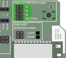
To enable the push button you have to connect the jumper on the BUTTON position. This will connect the push button to signal PB3.
RGB LED
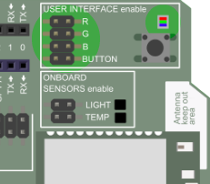
The RGB LED is enabled by connecting jumpers on the R, G and B positions. This will connect the LED as follows:
| Color | Pin |
|---|---|
| Red | PC1 |
| Green | PC2 |
| Blue | PC3 |
Temperature & light sensors
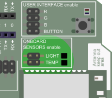
The development board is populated with two sensors:
-
Temperature sensor
-
Texas Instruments LMT86 (datasheet)
-
Osram SFH 5711 (datasheet)
Both sensors are analog sensors that are enabled by connecting the corresponding jumper. The connection is as in the table below:
| Sensor | Pin |
|---|---|
| Temperature | PA6 (ADC2) |
| Light | PA7 (ADC3) |
Flashing
Flashing of the Mira module is performed via the USB Serial interface using the LumenRadio provided flashing tool.