System Overview
The W-Modbus module require basic components to communicate and set various configurations on the CPU.
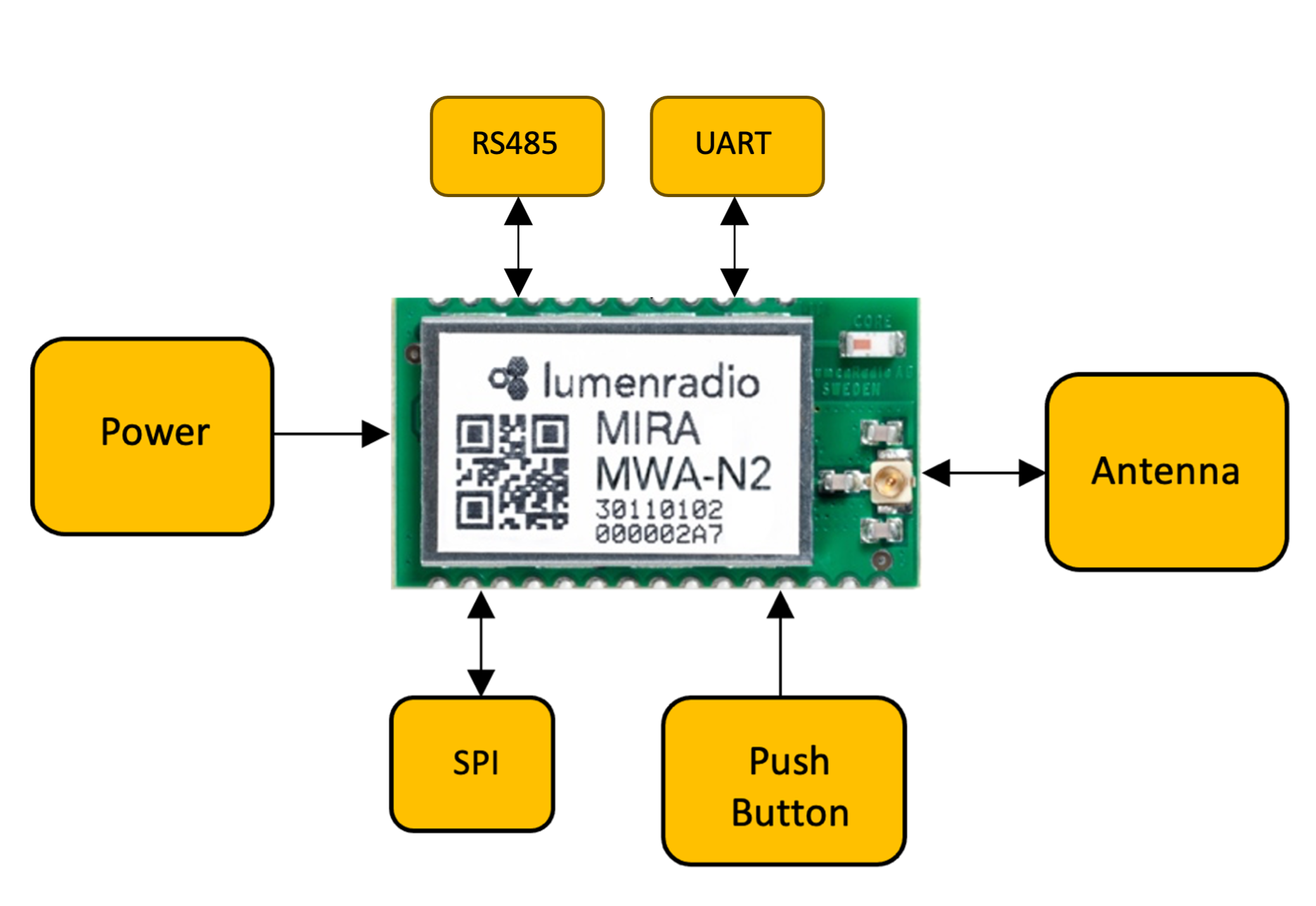 Block diagram of a functional system
The UART/RS485 pins are used to connect Modbus sensors/devices to the module. The SPI slave interface provides means to configurate the module. The push button is optional since the SPI interface provides the same functionality, and in that case the bootloader/button pin should be pulled high to 3.3V and not be left floating.
External antenna is mandatory, and uses an IPEX/u.fl connection that provides the range when communicating with other devices on the network. The module should be powered with 3.3V.