SPI Interface
The Serial Peripheral Interface (SPI) allows for communication with and configuration of the W-BACnet module.
The SPI is initialized 1500 ms after the W-BACnet module has started
booting. Attempts to communicate with the module via the SPI before 1500 ms
can yield unexpected results.
A reset of the SPI master or interruptions on the chip select line may cause the module to become unresponsive. It takes 5 seconds for the module to recover, and any SPI transactions attempted during this time will time out.
Interface Description
The interface is comprised of five digital signals (VDD max):
- IRQ: Interrupt Request; active low, configurable with the
IRQ_MASKregister - CS: Chip Select, active low
- SCK: Serial Clock
- MOSI: Master Output, Slave Input
- MISO: Master Input, Slave Output
Bit and Byte Order
The data on the SPI bus is clocked with most significant bit first. All multi-byte register data is sent in big-endian byte order.
Clock polarity
Data is valid in the low-to-high transition of SCK. In other words, the clock is active high with valid data on the leading clock edge.
Maximum clock speed
The maximum clock speed supported by W-BACnet is 4 MHz. Clock speeds
above this limit may result in unexpected behavior.
Setup time
The SPI slave unit has a setup time of 4 μs after the high-to-low transition
of the CS signal.
SPI transactions
All SPI transactions start with a high-to-low transition on the CS pin. The CS pin must be held low during the entire SPI transaction.
The IRQ_FLAGS register is always shifted out as the first byte
of each transaction.
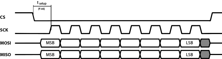 Example SPI transaction
SPI commands
All SPI command sequences, except for the NOP command, consist of two SPI
transactions. The first transaction uses two bytes, which denotes the
command. The second transaction, which carries the payload, must not be started until
the W-BACnet module has acknowledged the command with a high-to-low
transition on the IRQ pin. The first byte sent in the second
transaction will be ignored, however the recommended byte to send is 0xFF. See
below for a full SPI sequence example.
![]() Example SPI command sequence with a pending IRQ when sequence started
Example SPI command sequence with a pending IRQ when sequence started
The available SPI commands are listed in the table below. XX represents any
valid 1-byte register address, and -- represents values that are ignored.
| Command | Hex value | Description |
|---|---|---|
READ_REG |
0x00XX |
Read from a register. |
WRITE_REG |
0x01XX |
Write to a register. |
NOP |
0xFF-- |
NO Operation. Can be used as a shortcut to read the IRQ_FLAGS register. Last byte is not used. |
Interrupts
The IRQ pin is used to indicate two things:
- There are pending interrupt(s) that were enabled through the
IRQ_MASKregister. - The SPI slave is ready for the second transaction of an ongoing SPI command sequence.
The IRQ pin will always go high (inactive) after a successful SPI transaction.
A high-to-low transition will commence on the pin when interrupts are pending, or when the chip is ready for the second transaction in a SPI command sequence.
Registers
Below are a list of all registers available for interaction with the SPI. The
first column shows the single byte address of each register. The second column
contains register and field names. All fields within a register are indented in
a tree structure to indicate which register they belong to. The third column,
"Bit", denotes which bit positions inside the register is occupied by the
field. The "Type" column denotes whether the register is read-only (R),
write-only (W), or read-write (R/W).
The final column, "Reset value", denotes the default value of each field,
specified in hexadecimal format. That is, when the module comes factory new, or
after DEVICE_RESET has been set to 1, the registers will revert to their
reset values. A reset value of - means either the register is write-only, or
that it can be change depending on circumstance. For instance, the reset value
of ANTENNA_SELECTOR depends on if the module is an MWA-N2 or MWA-N3 module
since only the N3 has an internal antenna (see Integration page for information about MWA's).
| Address | Name | Bit | Type | Reset value |
|---|---|---|---|---|
0x00 |
STATUS |
|||
0x00 |
NETWORK_STATUS |
0 — 6 |
R |
- |
0x00 |
COMMISSIONING |
7 |
R/W |
0 |
0x01 |
MODE |
|||
0x01 |
APP_MODE |
0 — 6 |
R/W |
0 |
0x01 |
BOOTLOADER_ENABLED |
7 |
W |
- |
0x02 |
IRQ_MASK |
|||
0x02 |
NETWORK_STATUS_EN |
0 |
R/W |
1 |
0x02 |
PING_EN |
1 |
R/W |
1 |
0x02 |
RESERVED |
2 — 7 |
R/W |
- |
0x03 |
IRQ_FLAGS |
|||
0x03 |
NETWORK_STATUS |
0 |
R |
0 |
0x03 |
PING |
1 |
R |
1 |
0x03 |
RESERVED |
2 — 6 |
- |
|
0x03 |
TRANSACTION_ERROR |
7 |
R |
0 |
0x04 |
VERSION |
|||
0x04 |
FIRMWARE_VERSION_MAJOR |
0 — 7 |
R |
- |
0x04 |
FIRMWARE_VERSION_MINOR |
8 — 15 |
R |
- |
0x04 |
FIRMWARE_VERSION_PATCH |
16 — 23 |
R |
- |
0x06 |
RS485_CONFIG |
|||
0x06 |
BAUDRATE |
0 — 23 |
R/W |
0 |
0x06 |
RESERVED |
24 — 31 |
- |
|
0x07 |
RESET |
|||
0x07 |
DEVICE_RESET |
0 |
W |
- |
0x07 |
NETWORK_RESET |
1 |
W |
- |
0x07 |
RESERVED |
2 — 7 |
- |
- |
0x10 |
BACNET_STATUS |
|||
0x10 |
SERVER_ADDRESSES |
0 — 127 |
R/W |
FF..FF |
0x20 |
GENERAL_REQUESTS |
|||
0x20 |
ANTENNA_SELECTOR |
0 — 1 |
R/W |
- |
0x20 |
BLUETOOTH_ENABLED |
2 |
R/W |
- |
0x20 |
PROTOCOL_SELECTOR |
3 - 4 |
R/W |
- |
0x20 |
RESERVED |
5 — 7 |
- |
|
0x30 |
DEVICE_NAME |
|||
0x30 |
ASCII_CHARACTERS |
0 — 160 |
R/W |
FF..FF |
0x40 |
PING |
|||
0x40 |
PING_STATUS |
0 |
R |
- |
STATUS
This register contains information about the networking status of the device.
NETWORK_STATUS
This field is read-only and indicates roughly how stable the connection to the network is.
To perform successful network operations (e.g., modifying network baudrate or
app mode), it is recommended to do them when the value of NETWORK_STATUS is
1 or 2.
Devices in gateway modes will always have the value 1 in this field, since
link quality is measured in relation to the gateway.
| Value | Meaning |
|---|---|
0 |
Not connected to a network |
1 |
Connected, good link |
2 |
Connected, ok link |
3 |
Connected, unreliable link |
COMMISSIONING
This field is read-write, and indicates whether the device has yet received network commissioning data.
Setting this bit to 1 factory resets the device, which has the exact same
effect as setting DEVICE_RESET to 1. Note that this action
will revert the COMMISSIONING field to 0. See the
DEVICE_RESET section for more information about this
behavior.
The table below outlines the meaning of each value when read, along with the corresponding number of restarts that occur when writing the value:
| Value | Meaning (when read) | Restarts (when written) |
|---|---|---|
0 |
No commissioning data yet received | 0 |
1 |
Valid commissioning data received | 2 |
MODE
This register contains information about the current state of the application.
APP_MODE
This field is read-write, and determines which application mode the device is
in. The module, when factory new, boots into mode 0 (None). This is
detected by the application, leading to a switch to the default mode 4
(Commissioning Mesh Mode), causing a restart. In other words, the module
will restart once after booting in a factory new state. Writing the value 1
to DEVICE RESET will manually factory reset the device. In
other words, writing a 0 or 4 to APP_MODE will put the device in
Commissioning Mesh Mode.
The Idle mode will prevent the module from performing any networking,
therefore putting it in a sort of sleep. No configuration will be erased when
switching to this mode, meaning the module can be put back into secure mode and
connect to a previously saved network.
Read more about app modes in the Functional Description which describes the commissioning/decommissioning process.
The table below has a list of all possible modes, along with how many restarts are followed by the switching to a particular mode:
| Value | Meaning | Restarts (when written) |
|---|---|---|
0 |
None (will revert to default) | 2 |
1 |
Secure Gateway Mode | 1 |
2 |
Commissioning Gateway Mode | 1 |
3 |
Secure Mesh Mode | 1 |
4 |
Commissioning Mesh Mode (default) | 1 |
5 |
Idle Mode | 1 |
BOOTLOADER_ENABLED
This field is write-only. Set this bit to 1 in order to put device in
bootloader/DFU mode.
| Value | Meaning | Restarts (when written) |
|---|---|---|
1 |
Enter bootloader/DFU mode | 1 |
IRQ_MASK
This register is responsible for enabling/disabling interrupts.
NETWORK_STATUS_EN
This field is read-write, and enables or disables the network status interrupt.
| Value | Meaning |
|---|---|
0 |
Disable Network Status IRQ |
1 |
Enable Network Status IRQ |
PING_EN
This field is read-write, and enables or disables the ping interrupt.
| Value | Meaning |
|---|---|
0 |
Disable Ping IRQ |
1 |
Enable Ping IRQ |
IRQ_FLAGS
See the section about interrupts to find out more about how
these flags are checked.
IRQ_FLAG NETWORK_STATUS
Asserted when the NETWORK_STATUS field has changed
value. Only valid for devices that are in either Commissioning Mesh Mode
(4) or Secure mesh Mode (3) (see section about MODE).
The flag is cleared when the STATUS register is read, which
includes the NETWORK_STATUS field.
IRQ_FLAG PING
Asserted when the PING field is set to 1.
The flag is cleared when the PING register is read.
The flag should be cleared as soon as possible to avoid missing subsequent pings.
IRQ_FLAG TRANSACTION_ERROR
This bit MUST be observed. A 1 in this bit means that the SPI slave module
cannot process the current transaction, and the full command sequence must be
retransmitted.
VERSION
This register is read-only, and contains the version currently running on the device.
FIRMWARE_VERSION
This field contains three bytes: the major, minor and patch version installed on the device. The latest firmware can be found on our website and can be installed by following the steps mentioned in the firmware update documentation.
RS485_CONFIG
This register is read-write, and is used to configure and read the RS485 bus configuration, i.e. baudrate.
BAUDRATE
Standard values (in bits/second) 9600 bps, 19200 bps, 38400 bps, 76800
bps have been tested and verified. Larger values, such as 115200 bps, are
allowed but have not been tested. The default baudrate is 0 bps.
RESET
This register facilitates the wiping of configurations on the device.
DEVICE_RESET
This field is write-only, and allows the module to be manually factory reset. Factory resetting the module means restoring the device to the state it was on first boot by wiping any modified configurations. This action wipes network credentials, RS485 configurations, and reverts all registers and fields to their reset/default values (found here).
Performing a device reset leads to 2 restarts of the device, the first one after
wiping the configuration, which also sets MODE to 0. After
restarting the first time, the application will detect that MODE
is 0, leading to a switch to the default app mode, 4. This switch leads to
the additional restart, after which the device will be in mesh commissioning
mode. Read more about this behavior in the MODE section.
| Value | Meaning (when written) | Restarts (when written) |
|---|---|---|
1 |
Perform a factory reset | 2 |
NETWORK_RESET
This field is write-only, and when set to 1, wipes any saved network
credentials. Configurations other than the network, like the RS485 bus
parameters, will remain unaffected.
In practice, this means that devices in Secure Mesh Mode or Commissioning Mesh Mode will leave any joined network. For nodes in any of the gateway app modes, a network reset will clear previously saved network credentials. This can happen if the device was previously in a mesh mode and connected to a network, but was later switched to a gateway.
| Value | Meaning (when written) | Restarts (when written) |
|---|---|---|
1 |
Wipe network credentials | 1 if in Secure Mesh Mode, 0 otherwise |
BACNET_STATUS
This register is used to fetch BACnet related data from the device.
SERVER_ADDRESSES
This field is contains the single-byte address of each set or detected BACnet device. Any byte equal to 0xFF is equivalent to an "empty slot",
i.e. no address is present there.
| Value | Meaning |
|---|---|
0xFF |
No BACnet MS/TP Device set or detected |
| Anything else | Address of set or detected BACnet MS/TP Device |
GENERAL_REQUESTS
This register contains fields that are used to perform various application-related actions.
ANTENNA_SELECTOR
This register facilitates the selection of either the internal antenna or the external antenna for wireless communication. An antenna switch will always be followed by a restart.
NOTE: MWA-N2 modules do not have internal antennas, meaning they should not change this field under any circumstances (see Integration page for information about MWA's).
| Value | Meaning | Restarts (when switched to) |
|---|---|---|
1 |
Internal antenna selected | 1 |
2 |
External antenna selected | 1 |
BLUETOOTH_ENABLED
This field is read-write, and is used to control Bluetooth Low Energy (BLE) advertising for connections to our app. The device will advertise for 3 minutes after Bluetooth is activated. The W-BACnet app can be downloaded from the App store and Play store.
When connecting the app to a secure gateway with a firmware version of 3.1.0 or later, the app allows for updating of the firmware, and for an overview of the "network map". It is also possible to view the currently installed firmware version.
The network map shows how many devices are on the network, and how their packets are routed through the mesh network. The network map also shows which BACnet addresses have been connected to which W-BACnet device. It is also possible to name W-BACnet devices.
It is possible to connect the app to a mesh node, but functionality is limited to viewing the firmware version.
| Value | Meaning (when written) |
|---|---|
0 |
BLE advertising disabled |
1 |
BLE advertising enabled |
PROTOCOL_SELECTOR
Read or change the active communication protocol.
| Value | Meaning |
|---|---|
1 |
Modbus protocol is active |
2 |
BACnet protocol is active |
DEVICE_NAME
This register is read-write and can be used to get or set the current device name. The device name is used to identify a device in the W-BACnet app. The maximum allowed device name length is 20 bytes, where each byte contains one printable ASCII character.
ASCII_CHARACTERS
Each byte contains one printable ASCII character, up to a maximum of 20 bytes.
PING
This register facilitates the device ping functionality.
Ping is a command which can be sent from the W-BACnet app to help locate the device. On the W-BACnet boxed products, for example, the LEDs will flash.
When the OEM module is pinged, it will respond by setting the PING_STATUS field to 1. If the ping irq flag is enabled, an interrupt will be raised when the device is pinged.
The ping status and ping irq flag will be cleared when the PING_STATUS field is read.
PING_STATUS
This field is read-only, and is used to read ping status for the device.
When the device is pinged from the mobile app, the field will be set to 1.
Reading this field clears the status and the ping irq flag, if enabled.
Usage example
Below is a simple pseudo code example for reading the RS485 configuration using the SPI. It is assumed that the SPI is initialized this code is run.
/* Buffers must be large enough to accommodate register and commands */
uint8_t rx_buffer[BUF_SZ];
uint8_t tx_command[2];

tx_command[0] = 0x00; // Read command
tx_command[1] = 0x06; // Address of RS485 config

/* Transfer command bytes, read back IRQ flags in the first byte
spi_transfer(tx_command, 2, rx_buffer, 1);

/* Wait until the transfer completes */
WAIT_UNTIL(spi_transfer_complete());

 /* Wait for the IRQ indicating response is ready */
WAIT_UNTIL(gpio_value(SPI_IRQ) == 0);

/* Read the value. The RS485 config is 3 bytes long, plus one for IRQ flags */
spi_transfer(tx_command, 2, rx_buffer, 3 + 1);

/* Wait until the transfer completes */
WAIT_UNTIL(spi_transfer_complete());

/* IRQ flags are stored in rx_buf[0] */

/* Baudrate is multibyte, MSB first */
uint32_t baudrate = (rx_buf[1] << 16) |
                    (rx_buf[2] << 8) |
                    (rx_buf[3] << 0);

/* Parity is a simple boolean value in bit 24, i.e at position 0 in byte 4 */
uint8_t parity = (rx_buf[4] & 0x01);

/* Stop bits is a simple boolean value in bit 25, i.e at position 1 in byte 4 */
uint8_t stop_bits = (rx_buf[4] & 0x02) >> 1;