Pin assignments
Pin functions
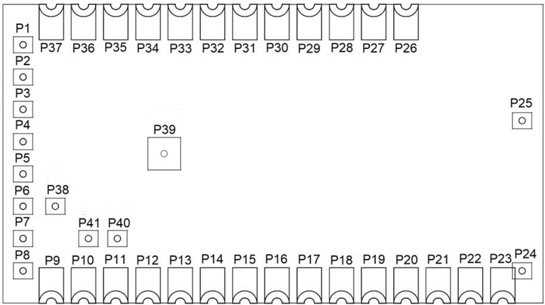 W-BACnet module seen from the top
| Pin number | Pin name | Pin type | Description | NRF52840 pin name |
|---|---|---|---|---|
| P1 | VSS | Power | Ground (0 V) | GND |
| P2 | MOSI | Digital input | SPI Master Out, Slave In | P0.04/AIN |
| P3 | N.C. | No connection | Do not connect | P0.05/AIN |
| P4 | N.C. | No connection | Do not connect | P0.06 |
| P5 | N.C. | No connection | Do not connect | P0.08 |
| P6 | MISO | Digital output | SPI Master In, Slave Out | P1.08 |
| P7 | VSS | Power | Ground (0 V) | GND |
| P8 | UART_TXD | Digital output | RS485 TX | P1.09 |
| P9 | VSS | Power | Ground (0 V) | GND |
| P10 | RS485_DE | Digital output | RS485 Driver enable | P0.12 |
| P11 | RS485_RE | Digital output | RS485 Receiver enable | P0.11 |
| P12 | nRESET | Digital input | Reset Pin (active low, external pull-up) | P0.18/nRESET |
| P13 | N.C. | No connection | Do not connect | P0.20 |
| P14 | N.C. | No connection | Do not connect | P0.22 |
| P15 | UART_RXD | Digital input | RS485 RX | P0.23 |
| P16 | SCK | Digital input | SPI Clock | P0.24 |
| P17 | N.C. | No connection | Do not connect | P1.00 |
| P18 | N.C. | No connection | Do not connect | P0.10/NFC |
| P19 | N.C. | No connection | Do not connect | P0.09/NFC |
| P20 | SWDIO | Digital input/output | SWD Interface Data | SWDIO |
| P21 | SWDCLK | Digital input | SWD Interface Clock | SWDCLK |
| P22 | N.C. | No connection | Do not connect | P1.02 |
| P23 | VSS | Power | Ground (0 V) | GND |
| P24 | VSS | Power | Ground (0 V) | GND |
| P25 | VSS | Power | Ground (0 V) | GND |
| P26 | VSS | Power | Ground (0 V) | GND |
| P27 | VSS | Power | Ground (0 V) | GND |
| P28* | IRQ | Digital output | SPI Interrupt signal, active low | P1.13 |
| P29* | N.C. | No connection | Do not connect | P1.15 |
| P30* | N.C. | No connection | Do not connect | P0.03/AIN |
| P31* | N.C. | No connection | Do not connect | P0.02/AIN |
| P32* | BOOTLOADER | Digital input | Bootloader entry (active low, external pull-up | P0.28/AIN |
| P33* | CS | Digital output | SPI Chip select, active low | P0.29/AIN |
| P34* | UART_MGMT_TX | Digital output | UART management TX | P0.30/AIN |
| P35* | UART_MGMT_RX | Digital input | UART management RX | P0.31/AIN |
| P36 | VDD | Power | Power supply (3.3 V) | 3V3 |
| P37 | VSS | Power | Ground (0 V) | GND |
| P38 | N.C. | No connection | Do not connect | Vbus |
| P39 | VSS | Power | Ground (0 V) | GND |
| P40 | N.C. | No connection | Do not connect | USB_P |
| P41 | N.C. | No connection | Do not connect | USB_N |
* : Low frequency I/O (up to 10 kHz). For detailed information about pin functionality, see the Nordic Semiconductor nRF52840 product specification document.
RF Antenna connector
When connecting an external antenna the u.FL on the top of the module shall be used. The antenna shall have the characteristic impedance of 50 ohm at 2.45 GHz. See the Antenna guideline for more information.