SPI Interface
The SPI interface gives access to all features of the TimoTwo module. The interface consists of five digital signals (VDD max):
-
IRQ – Interrupt signal. Active low, configurable through the interrupt mask register
-
CS – SPI Chip select, active low
-
SCK – SPI clock input
-
MOSI – SPI data input
-
MISO – SPI data output
Interface description
Bit and byte order
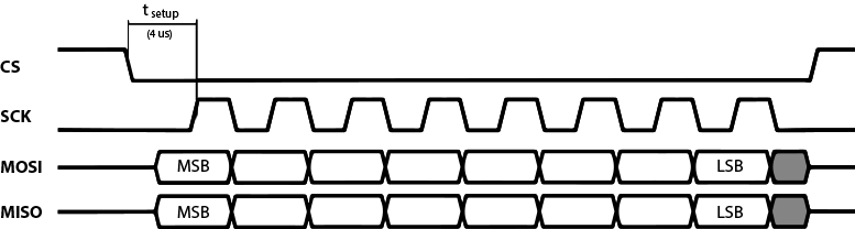
The data on the SPI bus is clocked with most significant bit first. All multi-byte register data are sent in big-endian byte order (aka. network byte order). In the tables below, bytes are numbered so that byte 0 is the first payload byte being sent on the SPI bus, byte 1 is the secod payload byte, etc.
Clock polarity
Data is valid in the low-to-high transition of SCK. This is also known as the clock being active high with valid data on the leading clock edge.
Maximum clock speed
The maximum clock speed supported by TimoTwo is 2MHz. Clock speeds above this limit may result in unexpected behavior.
Setup time
The SPI slave unit has a setup time of 4 μs after the high-to-low transition of the CS signal.
SPI operation
SPI transactions
All SPI transactions start with a high-to-low transition on the CS pin. The CS pin must be held low during the entire SPI transaction.
The IRQ_FLAGS register is always shifted out as the first byte of each
transaction.
 Example SPI transaction
SPI commands
All SPI command sequences, except for the NOP command, consist of two
SPI transactions. The first transaction shall be one byte long, this is
the command byte. The second transaction is the payload. The second
transaction must not be started until the TimoTwo module has confirmed the
command by a high-to-low transition on the IRQ pin. The first byte being
sent to TimoTwo in the second transaction will be ignored, however it is
suggested this byte is being sent as 0xFF.
The IRQ signal will stay low during the processing of the command after the payload has been transferred. When the command has been processed, the IRQ signal goes high. It is mandatory to wait for the previous command to finish processing before any consecutive commands are being sent.
See below for an example full SPI command sequence.
NOTE: Bit 7 in the IRQ flags register MUST be observed. A 1 in
this bit means that the SPI slave module is unable to process the
current transaction, and the full command sequence MUST be restarted –
this means sending the command transaction again.
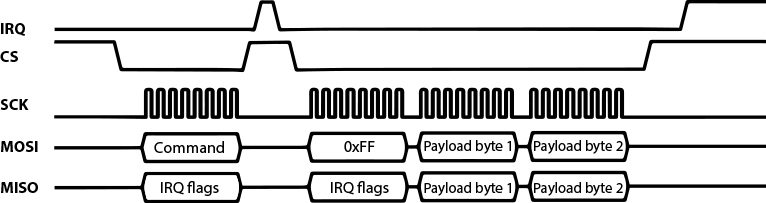 Example SPI command sequence with a pending IRQ when sequence started
The available SPI commands are listed in the table below.
| Command | Binary value | Comment |
|---|---|---|
| WRITE_REG | 01AA AAAA |
Write to a register. AAAAAA = 6 bit register address. |
| READ_REG | 00AA AAAA |
Read from a register. AAAAAA = 6 bit register address. |
| READ_DMX | 1000 0001 |
Read the latest received DMX values from the window set up by the DMX_WINDOW register. |
| READ_ASC | 1000 0010 |
Read the latest received ASC frame. |
| READ_RDM | 1000 0011 |
Read the received RDM request (RX mode) or response (TX mode). |
| READ_RXTX | 1000 0100 |
Read available RXTX interface data. |
| WRITE_DMX | 1001 0001 |
Write DMX to the internal DMX generation buffer. |
| WRITE_RDM | 1001 0010 |
Write an RDM response (RX mode) or RDM request (TX mode). |
| WRITE_RXTX | 1001 0011 |
Write RXTX interface data. |
| RADIO_DISCOVERY | 1010 0000 |
Write Radio DUB command. |
| RADIO_DISCOVERY_RESULT | 1010 0001 |
Read Radio DUB result. |
| RADIO_MUTE | 1010 0010 |
Write Radio mute command. |
| RADIO_MUTE_RESULT | 1010 0011 |
Read Radio mute response. |
| RDM_DISCOVERY | 1010 0100 |
Write RDM DUB command. |
| RDM_DISCOVERY_RESULT | 1010 0101 |
Read RDM DUB result. |
| NODE_QUERY | 1010 0110 |
Write radio node query command. |
| NODE_QUERY_RESPONSE | 1010 0111 |
Read radio node query response. |
| NOP | 1111 1111 |
No operation. Can be used as a shortcut to read the IRQ_FLAGS register. |
For more information on the RDM commands, see the RDM section.
Registers
All reserved bits in the registers shall be considered reserved for future use - don't care when read, write as 0.
Bits in registered is numbered so that bit 0 is least significant bit.
Do not read or write undefined registers – doing so could result in undefined behavior.
| Address (hex) | Mnemonic | Description | Comment |
|---|---|---|---|
| 0x00 | CONFIG |
Configuration register | Write may cause reboot |
| 0x01 | STATUS |
Device status register | |
| 0x02 | IRQ_MASK |
IRQ mask register | |
| 0x03 | IRQ_FLAGS |
IRQ flags register | |
| 0x04 | DMX_WINDOW |
DMX windows configuration register | |
| 0x05 | ASC_FRAME |
Alternate start code frame informatiom register | |
| 0x06 | LINK_QUALITY |
Wireless link signal quality register | |
| 0x08 | DMX_SPEC |
DMX parameter register for internal DMX generation | |
| 0x09 | DMX_CONTROL |
Internal DMX generation control register | |
| 0x0A | EXTENDED_IRQ_MASK |
Extended IRQ mask register | |
| 0x0B | EXTENDED_IRQ_FLAGS |
Extended IRQ flags register | |
| 0x0C | RF_PROTOCOL |
Transmission protocol selection | Write may cause reboot |
| 0x0D | DMX_SOURCE |
DMX source information register | |
| 0x0E | LOLLIPOP |
Lollipop counter register | |
| 0x10 | VERSION |
Version register | |
| 0x11 | RF_POWER |
RF power configuration register | |
| 0x12 | BLOCKED_CHANNELS |
Channel blocking configuration register | |
| 0x20 | BINDING_UID |
RDM binding UID register | |
| 0x21 | LINKING_KEY |
Linking key register | Write may cause reboot |
| 0x30 | BLE_STATUS |
BLE status register | Write may cause reboot |
| 0x31 | BLE_PIN |
BLE PIN code register | Write may cause reboot |
| 0x32 | BATTERY |
BLE battery status register | |
| 0x33 | UNIVERSE_COLOR |
Universe color register | |
| 0x34 | OEM_INFO |
OEM device information register | |
| 0x35 | RXTX_STATUS |
Status register for the BLE RX/TX service | |
| 0x36 | DEVICE_NAME |
Device name register | |
| 0x37 | UNIVERSE_NAME |
Universe name register | |
| 0x3D | INSTALLED_OPTIONS |
Installed options register | |
| 0x3F | PRODUCT_ID |
Product ID register |
CONFIG register (0x00)
| Byte | Bit | Mnemonic | Type | Reset value | Description |
|---|---|---|---|---|---|
| 0 | 7 | RADIO_ENABLE | R/W | 1 | Enable wireless operation.0 = Disabled1 = Enabled |
| 6-4 | Reserved | - | - | Reserved for future use | |
| 3 | SPI_RDM | R/W | - | 0 = UART RDM is used1 = SPI RDM is used |
|
| 2 | Reserved | - | - | Reserved for future use | |
| 1 | RADIO_TX_RX_MODE | R/W | - | 0 = Receiver1 = Transmitter |
|
| 0 | UART_EN | R/W | 1 | Enable UART output of DMX frames.0 = Disabled1 = Enabled |
|
RADIO_ENABLE
When disabling wireless operation, this only affects the wireless DMX operation, Bluetooth is independently controlled via BLE_STATUSregister.
SPI_RDM
In receiver mode only. Selects if SPI or UART shall be used for RDM commands.
RADIO_TX_RX_MODE
Writing this bit changes between RX and TX mode.
Note: When mode is changed from RX to TX or vice versa, the module will restart and all registers will revert to their respective reset values.
UART_EN
This bit enables or disables the UART input/output of DMX and RDM data.
STATUS register (0x01)
| Byte | Bit | Mnemonic | Type | Reset value | Description |
|---|---|---|---|---|---|
| 0 | 7 | UPDATE_MODE | R | 0 | 0 = module operational1 = In software update mode |
| 6-4 | Reserved | - | - | Reserved for future use | |
| 3 | DMX | R | 0 | 0 = No DMX available1 = DMX available |
|
| 2 | IDENTIFY | R/W | 0 | 0 = No identify1 = RDM identify active |
|
| 1 | RF_LINK | R/W | 0 | 0 = No radio link1 = Active radio linkIn TX mode, write 1 to start linking |
|
| 0 | LINKED | R/W | - | 0 = Not linked1 = Linked to TX (or pairing)Write 1 to unlink |
|
UPDATE_MODE
This bit shows if the module is in update mode. When in update mode, some functions are limited.
DMX
In receiver mode this bit indicates that DMX data is being received either over the wireless DMX link, or via BLE.
In transmitter mode this bit indicates that DMX data is being received either via the UART interface, via BLE or if the internal DMX from SPI generation is active.
To get the current data source, read the DMX_SOURCE register.
IDENTIFY
In transmitter mode, writing 1 will start identifying all linked receivers, writing 0 will stop indentifying.
In receiver mode this is a read-only bit. Reading 1 means this device shall indetify.
RF_LINK
This bit shows the status of the wireless DMX link.
Ths bit is read-only in RX mode, writing 1to this bit in TX mode starts a linking process.
LINKED
This bit shows if the module is linked to a TX or not. Writing 1 to this bit performes an unlink operation.
IRQ_MASK register ( 0x02)
| Byte | Bit | Mnemonic | Type | Reset value | Description |
|---|---|---|---|---|---|
| 0 | 7 | Reserved | - | - | Reserved for future use |
| 6 | EXTENDED_IRQ_EN | R/W | 0 | Enable extended interrupts | |
| 5 | IDENTIFY_IRQ_EN | R/W | 0 | Enable identify device interrupt | |
| 4 | ASC_IRQ_EN | R/W | 0 | Enable alternative start code interrupt | |
| 3 | RF_LINK_IRQ_EN | R/W | 0 | Enable radio link status change interrupt | |
| 2 | DMX_CHANGED_IRQ_EN | R/W | 0 | Enable DMX changed interrupt | |
| 1 | LOST_DMX_IRQ_EN | R/W | 0 | Enable loss of DMX interrupt | |
| 0 | RX_DMX_IRQ_EN | R/W | 0 | Enable DMX frame reception interrupt | |
IRQ_FLAGS register (0x03)
| Byte | Bit | Mnemonic | Type | Reset value | Description |
|---|---|---|---|---|---|
| 0 | 7 | SPI_DEVICE_BUSY | R | 0 | SPI slave device is busy and cannot comply with command. Command sequence MUST be restarted. |
| 6 | EXTENDED_IRQ | R | 0 | Extended interrupt | |
| 5 | IDENTIFY_IRQ | R | 0 | Identify device state change interrupt | |
| 4 | ASC_IRQ | R | 0 | Alternative start code frame received interrupt | |
| 3 | RF_LINK_IRQ | R | 0 | Radio link status change interrupt | |
| 2 | DMX_CHANGED_IRQ | R | 0 | DMX changed in DMX window interrupt | |
| 1 | LOST_DMX_IRQ | R | 0 | Loss of DMX interrupt | |
| 0 | RX_DMX_IRQ | R | 0 | Complete DMX frame received interrupt | |
DMX_WINDOW register (0x04)
| Byte | Bit | Mnemonic | Type | Reset value | Description |
|---|---|---|---|---|---|
| 0 | 7-0 | WINDOW_SIZE_MSB | R/W | 0x02 | DMX windows size (MSB) |
| 1 | 7-0 | WINDOW_SIZE_LSB | R/W | 0x00 | DMX windows size (MSB) |
| 2 | 7-0 | START_ADDRESS_MSB | R/W | 0x00 | DMX start address (MSB) |
| 3 | 7-0 | START_ADDRESS_LSB | R/W | 0x00 | DMX start address (LSB) |
WINDOW_SIZE
The size of the DMX window to be used in number of bytes. It shall not span beyond the 512th slot. This is a 16 bit value that is written with MSB in byte 2 of this register, LSB in byte 3.
The reset value is a length of 512 bytes (the full universe).
START_ADDRESS
The DMX start address to be used, zero-indexed. Shall be within the range 0-511. This is a 16 bit value that is written with MSB in byte 0 of this register, LSB in byte 1.
ASC_FRAME register (0x05)
| Byte | Bit | Mnemonic | Type | Reset value | Description |
|---|---|---|---|---|---|
| 0 | 7-0 | ASC_FRAME_LENGTH_MSB | R | - | Length of received ASC frame (MSB) |
| 1 | 7-0 | ASC_FRAME_LENGTH_LSB | R | - | Length of received ASC frame (LSB) |
| 2 | 7-0 | START_CODE | R | - | Start code of received ASC frame |
Use READ_ASC command to read the ASC frame data after reading this register.
LINK_QUALITY register (0x06)
| Byte | Bit | Mnemonic | Type | Reset value | Description |
|---|---|---|---|---|---|
| 0 | 7-0 | PDR | R | - | Packet delivery rate |
PDR
Packet delivery rate to be displayed as percent: 0 = 0%, 255 = 100%.
This register is only available in RX mode.
DMX_SPEC register (0x08)
| Byte | Bit | Mnemonic | Type | Reset value | Description |
|---|---|---|---|---|---|
| 0 | 7-0 | N_CHANNELS_MSB | R/W | 0x02 | Number of slots/channels to generate (MSB) |
| 1 | 7-0 | N_CHANNELS_LSB | R/W | 0x00 | Number of slots/channels to generate (LSB) |
| 2 | 7-0 | INTERSLOT_TIME_MSB | R/W | 0x00 | Interslot spacing in µs (MSB) |
| 3 | 7-0 | INTERSLOT_TIME_LSB | R/W | 0x00 | Interslot spacing in µs (LSB) |
| 4 | 7-0 | REFRESH_PERIOD_MSB | R/W | 0x00 | DMX frame length in µs (MSB) |
| 5 | 7-0 | REFRESH_PERIOD_B2 | R/W | 0x00 | DMX frame length in µs |
| 6 | 7-0 | REFRESH_PERIOD_B1 | R/W | 0x61 | DMX frame length in µs |
| 7 | 7-0 | REFRESH_PERIOD_LSB | R/W | 0xA8 | DMX frame length in µs (LSB) |
This register is only available in TX mode.
REFRESH_PERIOD
The refresh period is the time between two consecutive BREAK conditions. The frame rate of the generated DMX stream will be 1/REFRESH_PERIOD. Defaults to 25000 µs (refresh rate of 40 Hz). This value is a 32 bit value.
INTERSLOT_TIME
The interslot time is the time between one slot's last stop bit to the next slot's start bit. The interslot time is a 16 bit value, and defaults to 0 µs.
N_CHANNELS
The number of channels/slots to generate. This is a 16 bit value from 1 to 512. This parameter defaults to 512.
DMX_CONTROL register (0x09)
| Byte | Bit | Mnemonic | Type | Reset value | Description |
|---|---|---|---|---|---|
| 0 | 7-1 | Reserved | - | - | Reserved for future use |
| 0 | ENABLE | R/W | 0 | 0 = internal generation disabled1 = internal generation enabled |
|
This register is only available in TX mode.
ENABLE
Starts or stops the internal DMX generation for DMX data from SPI. The DMX_SPECregister should
be set up before writing 1to this bit.
EXTENDED_IRQ_MASK register (0x0A)
| Byte | Bit | Mnemonic | Type | Reset value | Description |
|---|---|---|---|---|---|
| 0 | 7-0 | Reserved | R/W | - | Reserved for future use |
| 1 | 7-0 | Reserved | R/W | - | Reserved for future use |
| 2 | 7-0 | Reserved | R/W | - | Reserved for future use |
| 3 | 7 | NODE_QUERY_EN | R/W | 0 | Enable node query interrupt (TX mode) |
| 6 | UNIV_META_CHANGED_EN | R/W | 0 | Enable universe metadata changed interrupt (RX mode) | |
| 5 | RDM_DISCOVERY_EN | R/W | 0 | Enable RDM Discovery interrupt (TX mode) | |
| 4 | RADIO_MUTE_EN | R/W | 0 | Enable Radio Mute interrupt (TX mode) | |
| 3 | RADIO_DISCOVERY_EN | R/W | 0 | Enable Radio Discovery interrupt (TX mode) | |
| 2 | RXTX_CTS_EN | R/W | 0 | Enable RXTX clear to send interrupt | |
| 1 | RXTX_DA_EN | R/W | 0 | Enable RXTX data available interrupt | |
| 0 | RDM_IRQ_EN | R/W | 0 | Enable RDM request interrupt | |
EXTENDED_IRQ_FLAGS register (0x0B)
| Byte | Bit | Mnemonic | Type | Reset value | Description |
|---|---|---|---|---|---|
| 0 | 7-0 | Reserved | R/W | - | Reserved for future use |
| 1 | 7-0 | Reserved | R/W | - | Reserved for future use |
| 2 | 7-0 | Reserved | R/W | - | Reserved for future use |
| 3 | 7 | NODE_QUERY | R/W | 0 | Reponse from a node query command available (TX mode) |
| 6 | UNIV_META_CHANGED | R/W | 0 | Universe metadata changed (RX mode) | |
| 5 | RDM_DISCOVERY | R/W | 0 | RDM Discovery command finished (TX mode) | |
| 4 | RADIO_MUTE | R/W | 0 | Radio Mute command finished (TX mode) | |
| 3 | RADIO_DISCOVERY | R/W | 0 | Radio Discovery command finished (TX mode) | |
| 2 | RXTX_CTS | R/W | 0 | RXTX clear to send | |
| 1 | RXTX_DA | R/W | 0 | RXTX data available | |
| 0 | RDM_IRQ | R/W | 0 | RDM request available (RX mode), RDM response availabe (TX mode). | |
RF_PROTOCOL register (0x0C)
| Byte | Bit | Mnemonic | Type | Reset value | Description |
|---|---|---|---|---|---|
| 0 | 7-0 | TX_PROTOCOL | R/W | - | 0= CRMX1= W-DMX G33= W-DMX G4S |
TX_PROTOCOL
In TX mode it is possible to select what wireless protocol to transmit; CRMX, W-DMX G3 or W-DMX G4S.
DMX_SOURCE register (0x0D)
| Byte | Bit | Mnemonic | Type | Reset value | Description |
|---|---|---|---|---|---|
| 0 | 7-0 | DATA_SOURCE | R | - | 0= No data1= DMX port (UART2= Wireless DMX link3 = SPI4 = BLE |
DATA_SOURCE
This value indicates what data source that is currently active. If there is data active on more than one source, this field returns what source the module has picked based on its priority order.
LOLLIPOP register (0x0E)
| Byte | Bit | Mnemonic | Type | Reset value | Description |
|---|---|---|---|---|---|
| 0 | 7-0 | COUNTER | R/W | 0 | Lollipop counter |
COUNTER
This is a so called lollipop counter. It starts from 0 and is increased by 1 every time
it is read. When it reaches 255 it will wrap around down to 128. Hence it will never return
to a value below 128 unless the module has been rebooted.
This can be used for detecting module reboots by setting this counter to a value larger than 128
after everythng has been initialized. By periodically reading this counter, as soon as the counter
return a value less than 128 it is a sign that the module has rebooted.
After the module has been rebooted, non-volatile registers has returned to their specified reset values and should be re-initialized.
VERSION register (0x10)
| Byte | Bit | Mnemonic | Type | Reset value | Description |
|---|---|---|---|---|---|
| 0 | 7-0 | HW_VERSION_B4 | R | - | Hardware version (B4) |
| 1 | 7-0 | HW_VERSION_B3 | R | - | Hardware version (B3) |
| 2 | 7-0 | HW_VERSION_B2 | R | - | Hardware version (B2) |
| 3 | 7-0 | HW_VERSION_B1 | R | - | Hardware version (B1) |
| 4 | 7-0 | SW_VERSION_B4 | R | - | Software version (B4) |
| 5 | 7-0 | SW_VERSION_B3 | R | - | Software version (B3) |
| 6 | 7-0 | SW_VERSION_B2 | R | - | Software version (B2) |
| 7 | 7-0 | SW_VERSION_B1 | R | - | Software version (B1) |
HW_VERSION
The hardware version is written as a 8 digit hexadecimal number according to B4B3B2B1, for example 0000A003.
SW_VERSION
The software version is written as decimal numbers with points in between, like B4.B3.B2.B1, for example 1.0.7.2 or 1.0.5.35.
RF_POWER register (0x11)
| Byte | Bit | Mnemonic | Type | Reset value | Description |
|---|---|---|---|---|---|
| 0 | 7-0 | OUTPUT_POWER | R/W | 2 | RF Output power in transmitter mode |
OUTPUT_POWER
When in transmitter mode, the output power can be controlled by writing this register. The reset value is 18dBm, which results in ETSI compliant 100mW when using a 2dBi antenna.
| Value | Output power from 2dBi antenna |
|---|---|
| 2 | 20 dBm / 100 mW |
| 3 | 16 dBm / 40 mW |
| 4 | 11 dBm / 13 mW |
| 5 | 5 dBm / 3 mW |
BLOCKED_CHANNELS register (0x12)
| Byte | Bit | Mnemonic | Type | Reset value | Description |
|---|---|---|---|---|---|
| 0 | 7-0 | FLAGS | R/W | 0 | Channel 7-0 |
| 1 | 7-0 | FLAGS | R/W | 0 | Channel 15-8 |
| 2 | 7-0 | FLAGS | R/W | 0 | Channel 23-16 |
| 3 | 7-0 | FLAGS | R/W | 0 | Channel 31-24 |
| 4 | 7-0 | FLAGS | R/W | 0 | Channel 39-32 |
| 5 | 7-0 | FLAGS | R/W | 0 | Channel 47-40 |
| 6 | 7-0 | FLAGS | R/W | 0 | Channel 55-48 |
| 7 | 7-0 | FLAGS | R/W | 0 | Channel 63-56 |
| 8 | 7-0 | FLAGS | R/W | 0 | Channel 71-64 |
| 9 | 7-0 | FLAGS | R/W | 0 | Channel 79-72 |
| 10 | 7-0 | FLAGS | R/W | 0 | Channel 87-80 |
FLAGS
When in transmitter mode, the transmission channels can be blocked. TimoTwo always employ LumenRadio's patented Cognitive Coexistence technology, but still allow channels to be blocked completely. One channel is 1MHz wide, and the transmission channels are 2402-2480MHz, represented by channel numbers 2-80.
To block a channel, write a 1 to the corresponding bit in the BLOCKED_CHANNELS
register. Writing a 0 enables the channel to be used again.
Examples:
- Channel 2 is represented by bit 2 in byte 0
- Channel 14 is represented by bit 6 in byte 1
- Channel 80 is represented by bit 0 byte 10
Block flags written to bits correspondig to channels 0-1 and 81-87 will always be ignored.
At any given point at least 16 channels must be enabled. If less than 16 channels are used, TimoTwo will reset this register and allow transmission on all channels.
Note: For best performance, do not block more than half of the available channels. If blocking
more channels than are allowed by certification requirements this register will be reset to all 0.
BINDING_UID register (0x20)
| Byte | Bit | Mnemonic | Type | Reset value | Description |
|---|---|---|---|---|---|
| 0 | 7-0 | UID_MSB | R/W | 0 | RDM UID of the host device (MSB) |
| 1 | 7-0 | UID_B4 | R/W | 0 | RDM UID of the host device |
| 2 | 7-0 | UID_B3 | R/W | 0 | RDM UID of the host device |
| 3 | 7-0 | UID_B2 | R/W | 0 | RDM UID of the host device |
| 4 | 7-0 | UID_B1 | R/W | 0 | RDM UID of the host device |
| 5 | 7-0 | UID_LSB | R/W | 0 | RDM UID of the host device (LSB) |
UID
The binding UID is the fixture's UID that contain the TimoTwo module. This must be used whe using RDM over SPI. It is also recommended to use this when using RDM over UART. This binding UID corresponds to the binding UID in the E1.20 (RDM) standard, and may be used by smart RDM controllers to group devices together through the binding UID when RDM devices are located in the same physical device.
LINKING_KEY register (0x21)
This register has two different layouts depending on if operating in TX or RX mode. For security reasons, this register can not be read.
Note: Writing this register causes the module to restart and hence cause all non-volatile registers to revert to their respective reset values.
RX mode
| Byte | Bit | Mnemonic | Type | Reset value | Description |
|---|---|---|---|---|---|
| 0 | 7-0 | KEY1 | W | - | First digit of Linking key |
| 1 | 7-0 | KEY2 | W | - | 2nd digit of Linking key |
| 2 | 7-0 | KEY3 | W | - | 3rd digit of Linking key |
| 3 | 7-0 | KEY4 | W | - | 4th digit of Linking key |
| 4 | 7-0 | KEY5 | W | - | 5th digit of Linking key |
| 5 | 7-0 | KEY6 | W | - | 6th digit of Linking key |
| 6 | 7-0 | KEY7 | W | - | 7th digit of Linking key |
| 7 | 7-0 | KEY8 | W | - | Last digit of Linking key |
| 8 | 7-0 | MODE | W | - | What mode to run in0 = CRMX Classic1= CRMX2 |
| 9 | 7-0 | OUTPUT | W | - | Output number to link to (0 - 7) |
TX mode
| Byte | Bit | Mnemonic | Type | Reset value | Description |
|---|---|---|---|---|---|
| 0 | 7-0 | KEY1 | W | - | First digit of Linking key |
| 1 | 7-0 | KEY2 | W | - | 2nd digit of Linking key |
| 2 | 7-0 | KEY3 | W | - | 3rd digit of Linking key |
| 3 | 7-0 | KEY4 | W | - | 4th digit of Linking key |
| 4 | 7-0 | KEY5 | W | - | 5th digit of Linking key |
| 5 | 7-0 | KEY6 | W | - | 6th digit of Linking key |
| 6 | 7-0 | KEY7 | W | - | 7th digit of Linking key |
| 7 | 7-0 | KEY8 | W | - | Last digit of Linking key |
KEY
The key is an 8 digit code encoded into 8 bytes. For example 12345678 is written
as 0x01, 0x02, 0x03, 0x04, 0x05, 0x06, 0x07, 0x08.
To remove a custom linking key in TX mode, write 8 bytes of 255 (0xFF) as a key. This will revert back to the module's factory default key.
MODE
To link properly the mode of the transmitter needs to be written.
0x00: CRMX Classic0x01: CRMX2
Only available in RX mode.
OUTPUT
This field corresponds to the outputs of Stardust or similar multi-universe transmitters.
If linking to the first output of a Stardust (Output A), write 0x00 to this field, 0x01
for Output B, etc.
Note: In CRMX Classic mode, only every second value (0x00, 0x02, 0x04, 0x06) is available.
If linking to a single universe transmitter, for instance Aurora, only universe 0x00
and CRMX Classic mode is available.
Only available in RX mode.
Read more in the Linking Key section.
BLE_STATUS register (0x30)
| Byte | Bit | Mnemonic | Type | Reset value | Description |
|---|---|---|---|---|---|
| 0 | 7-2 | Reserved | - | - | Reserved for future use. |
| 1 | PIN_ACTIVE | R | - | 0 = BLE PIN is active1 = No BLE PIN active |
|
| 0 | BLE_ENABLE | R/W | - | 0 = BLE disabled1 = BLE enabled |
|
PIN_ACTIVE
This bit indicates if a PIN code is set and being used. To disable PIN, write the BLE_PINregister.
BLE_ENABLE
This bit indicates if BLE is enabled or disabled.
Note: When writing this bit to enable or disable the BLE stack the module will restart, hence all non-volatile registers will reset to their default values.
BLE_PIN register (0x31)
| Byte | Bit | Mnemonic | Type | Reset value | Description |
|---|---|---|---|---|---|
| 0 | 7-0 | PIN1 | W | - | First digit of PIN code |
| 1 | 7-0 | PIN2 | W | - | 2nd digit of PIN code |
| 2 | 7-0 | PIN3 | W | - | 3rd digit of PIN code |
| 3 | 7-0 | PIN4 | W | - | 4th digit of PIN code |
| 4 | 7-0 | PIN5 | W | - | 5th digit of PIN code |
| 5 | 7-0 | PIN6 | W | - | Last digit of PIN code |
The BLE_PIN register is used to enable or disable the PIN used for BLE communication.
Write the desired 6 digit PIN (ASCII 0-9) to this register to enable. To disable the
PIN code write 6 bytes of 255 (0xFF).
Note: After writing to this register the TimoTwo will restart and all non-volatile registers will reset to their default values.
BATTERY register (0x32)
The BATTERY register provides a way for a battery driven device to send the battery level via BLE.
This will be shown in the CRMX Toolbox app, or other apps that supports it.
| Byte | Bit | Mnemonic | Type | Reset value | Description |
|---|---|---|---|---|---|
| 0 | 7-0 | BATTERY_LEVEL | W | 255 | Battery level in percent. |
BATTERY_LEVEL
This value will be reported via the standard BLE Battery service.
0= 0%,100= 100%101-254are reserved values255= no battery available
UNIVERSE_COLOR register (0x33)
This register is read-only in RX mode and R/W in TX mode.
| Byte | Bit | Mnemonic | Type | Reset value | Description |
|---|---|---|---|---|---|
| 0 | 7-0 | RED | R/W | - | Red level (0 - 255) |
| 1 | 7-0 | GREEN | R/W | - | Green level (0 - 255) |
| 2 | 7-0 | BLUE | R/W | - | Blue level (0 - 255) |
RED/GREEN/BLUE
These bytes represent a 24 bit RGB value for the Universe color. In TX mode the written value will be propagated to all receivers that supports in. In RX mode this will show the color value that has been received from the transmitter. See theuniverse metadata section for more information.
OEM_INFO register (0x34)
The OEM_INFO register gives the manufacturer the possibility to let the CRMX Toolbox app,
or other apps that supports it, show custom images etc in the connection list. This will
make it easier for the end-user to distinguish different products from each other.
For more details about getting images added to the CRMX Toolbox app, please reach out to LumenRadio support.
| Byte | Bit | Mnemonic | Type | Reset value | Description |
|---|---|---|---|---|---|
| 0 | 7-0 | DEVICE_MODEL_ID_MSB | R/W | - | Device model ID (MSB) |
| 1 | 7-0 | DEVICE_MODEL_ID_LSB | R/W | - | Device model ID (LSB) |
| 2 | 7-0 | MANUFACTURER_ID_MSB | R/W | - | Manufacturer ID (MSB) |
| 3 | 7-0 | MANUFACTURER_ID_LSB | R/W | - | Manufacturer ID (LSB) |
DEVICE_MODEL_ID
This is the manufacturer's 16 bit device model ID as per the E1.20 (RDM) standard. Together with the Manufacturer ID it uniquely identifies a certail model from a certain manufacturer.
MANUFACTURER_ID
This is the manufacturer's ESTA registered 16 bit manufacturer ID.
RXTX_STATUS register
| Byte | Bit | Mnemonic | Type | Reset value | Description |
|---|---|---|---|---|---|
| 0 | 7-2 | Reserved | - | - | Reserved for future use |
| 1 | CLEAR_TO_SEND | R | 1 | Clear to write data to the RXTX interface | |
| 0 | DATA_AVAILABLE | R | 0 | There are data available to read in the RXTX interface | |
DEVICE_NAME register (0x36)
| Byte | Bit | Mnemonic | Type | Reset value | Description |
|---|---|---|---|---|---|
| 0 | 7-0 | DEVICE_NAME1 | R/W | - | Device name 1st character |
| 1 | 7-0 | DEVICE_NAME2 | R/W | - | Device name 2nd character |
| ... | ... | ... | R/W | - | Device name character 3 - 30 |
| 30 | 7-0 | DEVICE_NAME31 | R/W | - | Device name 31st character |
| 31 | 7-0 | DEVICE_NAME32 | R/W | - | Device name 32nd character |
DEVICE_NAME
The device name is a 32 character ASCII string. It is also used as the
device name in the Toolbox app, as well as DEVICE_LABEL in RDM.
For strings shorter than 32 characters the string shall be NULL terminated.
In TX mode the first 16 characters from this string will be transmitted as the universe name. For more information about universe name, see the universe metadata section.
UNIVERSE_NAME register (0x37)
This register is only available in RX mode.
| Byte | Bit | Mnemonic | Type | Reset value | Description |
|---|---|---|---|---|---|
| 0 | 7-0 | UNIVERSE_NAME1 | R | - | Device name 1st character |
| 1 | 7-0 | UNIVERSE_NAME2 | R | - | Device name 2nd character |
| ... | ... | ... | R | - | Device name character 3 - 14 |
| 14 | 7-0 | UNIVERSE_NAME15 | R | - | Device name 15st character |
| 15 | 7-0 | UNIVERSE_NAME16 | R | - | Device name 16st character |
UNIVERSE_NAME
Universe name is a 16 character ASCII string sent from a transmitter to indentify a transmitted universe as a human readable name.
For strings shorter than 16 characters the string will be NULL terminated.
For more information about universe name, see the universe metadata section.
INSTALLED_OPTIONS register (0x3D)
| Byte | Bit | Mnemonic | Type | Reset value | Description |
|---|---|---|---|---|---|
| 0 | 7-0 | N_OPTIONS | R | - | Number of installed options (0 - 6) |
| 1 | 7-0 | OPTION1_MSB | R | - | Installed option #1 ID (MSB) |
| 2 | 7-0 | OPTION1_LSB | R | - | Installed option #1 ID (LSB) |
| ... | ... | ... | R | - | Option 2-5... |
| 11 | 7-0 | OPTION6_MSB | R | - | Installed option #6 ID (MSB) |
| 12 | 7-0 | OPTION6_LSB | R | - | Installed option #6 ID (LSB) |
N_OPTIONS
This byte indicate how many options that has been installed and will be available in the following list.
OPTION1 - OPTION6
This is a list of N_OPTIONS 16 bit elements showing what options that has been installed.
The available options are:
| Option ID | Description |
|---|---|
0x2001 |
RDM TX via SPI |
0x2002 |
RDM TX via Proxy |
PRODUCT_ID register (0x3F)
| Byte | Bit | Mnemonic | Type | Reset value | Description |
|---|---|---|---|---|---|
| 0 | 7-0 | ID0 | R | - | Product ID byte 0 |
| 1 | 7-0 | ID1 | R | - | Product ID byte 1 |
| 2 | 7-0 | ID2 | R | - | Product ID byte 2 |
| 3 | 7-0 | ID3 | R | - | Product ID byte 4 |
ID
The product ID for TimoTwo is 0xF1, 0x40, 0x00, 0x00.
Interrupts
The IRQ pin is used to indicate that there is one (or more) pending interrupt that has been enabled through the IRQ_MASK register. The IRQ pin is also used to indicate that the SPI slave is ready to receive the second transaction of an ongoing SPI command sequence.
The IRQ pin will always go high (inactive) after a successful SPI transaction. If any interrupts are pending, or when the chip is ready for the second transaction in a SPI command sequence it will be indicated through a high-to-low transition on the IRQ pin.
RX_DMX_IRQ
Asserted when a complete DMX frame has been received. Cleared by issuing a READ_DMX command sequence.
Only available for receiver modules and TimoTwo FX in receiver mode.
LOST_DMX_IRQ
Asserted when DMX stream is lost. This may be an effect of losing radio link, or if DMX stream in to the transmitter is terminated (for instance the DMX cable to the transmitter is unplugged). Cleared by reading the STATUS register.
Only available for receiver modules and TimoTwo FX in receiver mode.
DMX_CHANGED_IRQ
Asserted when a complete DMX frame has been received and any slot within the DMX window has changed value. Cleared by issuing a READ_DMX command sequence.
Only available for receiver modules and TimoTwo FX in receiver mode.
RF_LINK_IRQ
Asserted whenever the state of the radio link has changed. This may be:
-
radio link is lost
-
radio link is established
-
receiver got paired to transmitter
-
receiver got unpaired from transmitter
Cleared by reading the STATUS register.
Only available for receiver modules and TimoTwo FX in receiver mode.
ASC_IRQ
Asserted when a complete ASC frame has been received. Cleared by reading the ASC_FRAME register.
Only available for receiver modules and TimoTwo FX in receiver mode.
IDENTIFY_IRQ
Asserted when TimoTwo is being told to start or stop it’s identify device procedure. For more information about identify, please refer to ”ANSI E1.20 - 2006 / Entertainment Technology-RDM-Remote Device Management over USITT DMX512 Networks” specification.
This bit is cleared by reading the STATUS register.
EXTENDED_IRQ
Asserted there is an IRQ in the extended IRQ range. Read the EXTENDED_IRQ_FLAGS register to obtain further details.
Extended IRQ_MASK
The EXTENDED_IRQ registers are used to control and read the extended interrupts as detailed below.
RDM
RX mode Asserted when there is an RDM request available to read. Cleared by issuing the READ_RDM command or if RDM request has timed out.
TX mode Asserted when there is an RDM response available, or when a request has timed out. Cleared by issuing the READ_RDM command.
RXTX_DA
Asserted when there is data available to read with the READ_RXTX command. Cleared by reading the data or by reading the RXTX_STATUS register.
RXTX_CTS
Asserted when it's safe to send more data to the RXTX interface. Cleared by writing data with the WRITE_RXTX command or by reading the RXTX_STATUS register.
UNIV_META_CHANGED
Asserted when universe color or universe name changes in RX mode. Cleared by reading any of those meta data registers.
RADIO_DISCOVERY
Asserted when a radio discover unique branch command has been completed. Cleared by reading the discovery result through the RADIO_DISCOVERY_RESULT command.
RADIO_MUTE
Asserted when a radio mute command has been completed. Cleared by reading the result through the RADIO_MUTE_RESPONSE command.
RDM_DISCOVER
Asserted when a RDM discover unique branch command has been completed. Cleared by reading the discovery result through the RDM_DISCOVERY_RESULT command.
NODE_QUERY
Asserted when a node query response is available or when the query has timed out. Cleared by reading the discovery result through the NODE_QUERY_RESPONSE command.