LED Outputs
Status LED
The status LED (STATUS_LED) indicates the status of TimoTwo module. The
LED indicator pin is an output pin capable of sourcing 5mA at the VDD
voltage. An appropriate current limiting resistor must be connected in
series with the LED. This LED is also used when using the link switch
based method of switching flex modes; please refer to flex mode page for
details.
Receiver
 Constant off (0V): Not linked to any transmitter
 Flashing: off (0V) 100 ms / on (VDD) 100 ms: linked to a transmitter,
but no active radio link
Flashing: off (0V) 100 ms / on (VDD) 100 ms: linked to a transmitter,
but no active radio link
 Flashing: off (0V) 900 ms / on (VDD) 100 ms: Active radio link, no DMX
present
Flashing: off (0V) 900 ms / on (VDD) 100 ms: Active radio link, no DMX
present
 Constant on (VDD): Active radio link, DMX data present
Transmitter
 Flashing: off (0V) 900 ms / on (VDD) 100 ms: Active radio link, no DMX
present
Flashing: off (0V) 900 ms / on (VDD) 100 ms: Active radio link, no DMX
present
 Constant on (VDD): Active radio link, DMX data present
 Flashing: off (0V) 100 ms / on (VDD) 100 ms: linking receivers
 Flashing: off (0V) 200 ms / on (VDD) 200 ms: unlinking receivers
Linked
Receiver
The Linked LED (LINKED) indicates whether the TimoTwo is linked to a
transmitter or if it’s available to be linked. High level (VDD) on
this pin indicates a linked state; low level (0V) indicates that the
TimoTwo module is not linked.
Transmitter
High level (VDD) on this pin indicates an ongoing linking activity; low level (0V) indicates that the TimoTwo module is currently not performing a linking activity.
RF Link
Receiver
A high level (VDD) on the RF Link LED output (RF_LINK) indicates
that the receiver is within range from the transmitter it is linked to
and that an active radio link from the transmitter is present.
Transmitter
A high level (VDD) on the RF Link LED output (RF_LINK) indicates
that there is an active radio link.
DMX LED
The DMX LED (DMX_LED) indicates if a valid DMX stream is received. A
high level (VDD) indicates that DMX is present, a low level (0V)
indicates that no valid DMX is present.
RDM LED
A high level (VDD) on the RDM LED output (RDM_LED) indicates that
the TimoTwo is performing RDM activity.
Radio level
TimoTwo has 5 output signals for controlling radio level LEDs in the form
of a bar graph (RDI_LVL0 - RDI_LVL4). Operation of these, and
suggestion of LED colors, can be found in the table below. These are
only used for receivers.
| Signal name | Suggested LED color | On when signal quality |
|---|---|---|
RDI_LVL0 |
Red | below 10% |
RDI_LVL1 |
Amber / Yellow | above 20% |
RDI_LVL2 |
Green | above 40% |
RDI_LVL3 |
Green | above 60% |
RDI_LVL4 |
Green | above 80% |
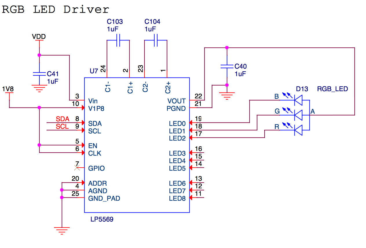
RGB LED
It is possible to connect an external RGB LED driver to the module's I2C
interface. The RGB LED will indicate the universe color at the same time as it acts
as the STATUS_LED, RF_LINK or the LINKED LEDs, depending on what LED output
of the driver IC that is used.
- Output 1 (
LED0-LED2): MimicsSTATUSLED - Output 2 (
LED3-LED5): MimicsRF_LINKLED - Output 3 (
LED6-LED8): MimicsLINKEDLED
For more information about universe color, see the universe metadata section.
Example schematic