SPI Interface
The SPI interface gives access to all features of the TiMo module. The interface consists of five digital signals (VDD max):
-
IRQ – Interrupt signal. Active low, configurable through the interrupt mask register
-
CS – SPI Chip select, active low
-
SCK – SPI clock input
-
MOSI – SPI data input
-
MISO – SPI data output
Interface description
Bit and byte order
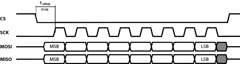
The data on the SPI bus is clocked with most significant bit first. All multi-byte register data are sent in big-endian byte order.
Clock polarity
Data is valid in the low-to-high transition of SCK. This is also known as the clock being active high with valid data on the leading clock edge.
Maximum clock speed
The maximum clock speed supported by TiMo is 2MHz. Clock speeds above this limit may result in unexpected behavior.
Setup time
The SPI slave unit has a setup time of 4 μs after the high-to-low transition of the CS signal.
SPI operation
SPI transactions
All SPI transactions start with a high-to-low transition on the CS pin. The CS pin must be held low during the entire SPI transaction.
The IRQ_FLAGS register is always shifted out as the first byte of each transaction.
 Example SPI transaction
SPI commands
All SPI command sequences, except for the NOP command, consist of two SPI transactions. The first transaction shall be one byte long, this is the command byte. The second transaction is the payload. The second transaction must not be started until the TiMo module has confirmed the command by a high-to-low transition on the IRQ pin. The first byte being sent to TiMo in the second transaction will be ignored, however it is suggested this byte is being sent as 0xFF. See below for an example full SPI command sequence.
NOTE: Bit 7 in the IRQ flags register MUST be observed. A ‘1’ in this bit means that the SPI slave module is unable to process the current transaction, and the full command sequence MUST be restarted – this means sending the command transaction again.
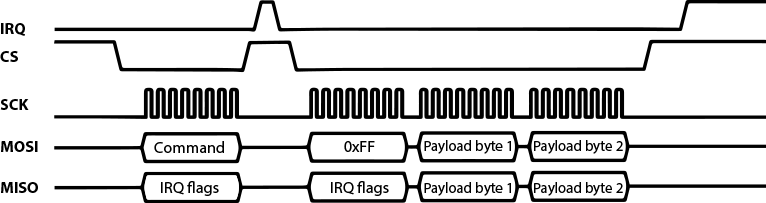 Example SPI command sequence with a pending IRQ when sequence started
The available SPI commands are listed in the table below.
| Command | Binary value | Comment |
|---|---|---|
| WRITE_REG | 01AA AAAA | Write to a register. AAAAAA = 6 bit register address. |
| READ_REG | 00AA AAAA | Read from a register. AAAAAA = 6 bit register address. |
| READ_DMX | 1000 0001 | Read the latest received DMX values from the window set up by the DMX_WINDOW register. |
| READ_ASC | 1000 0010 | Read the latest received ASC frame. |
| READ_RDM | 1000 0011 | Read the received RDM request. |
| WRITE_DMX | 1001 0001 | Write DMX to the internal DMX generation buffer. |
| WRITE_RDM | 1001 0010 | Write an RDM response. |
| NOP | 1111 1111 | No operation. Can be used as a shortcut to read the IRQ_FLAGS register. |
Register map
All undefined bits in the table below shall be considered reserved for future use - don't care when read, write as 0.
Do not read or write undefined registers – doing so could result in undefined behavior.
| Address (hex) | Mnemonic | Bit no. | Type | Reset value | Description |
|---|---|---|---|---|---|
| 00 | CONFIG | Configuration register | |||
| UART_EN | 0 | R/W | 1 | Enable UART output of DMX frames (required for RDM). 0 = Disabled, 1 = Enabled |
|
| RADIO_TX_RX_MODE | 1 | R/W | - | 0 = Receiver, 1 = Transmitter | |
| Reserved | 2 | - | - | Reserved for future use | |
| SPI_RDM | 3 | - | - | 0 = UART RDM is used, 1 = SPI RDM is used | |
| Reserved | 4-6 | - | - | Reserved for future use | |
| RADIO_ENABLE | 7 | R/W | 1 | Enable wireless operation. 1 = Enabled, 0 = Disabled |
|
| 01 | STATUS | Status register | |||
| LINKED | 0 | R/W | - | 0 = Not linked, 1 = Linked to TX (or pairing) Write 1 to unlink |
|
| RF_LINK | 1 | R/W | 0 | 0 = No radio link, 1 = Active radio link On transmitter, write 1 to start linking |
|
| IDENTIFY | 2 | R/W | 0 | 0 = No identify, 1 = RDM identify active | |
| DMX | 3 | R | 0 | 0 = No DMX available, 1 = DMX available | |
| Reserved | 4-6 | - | - | Reserved for future use | |
| UPDATE_MODE | 7 | R | 0 | 0 = chip operational, 1 = In driver update mode | |
| 02 | IRQ_MASK | IRQ mask register | |||
| RX_DMX_IRQ_EN | 0 | R/W | 0 | Enable DMX frame reception interrupt | |
| LOST_DMX_IRQ_EN | 1 | R/W | 0 | Enable loss of DMX interrupt | |
| DMX_CHANGED_IRQ_EN | 2 | R/W | 0 | Enable DMX changed interrupt | |
| RF_LINK_IRQ_EN | 3 | R/W | 0 | Enable radio link status change interrupt | |
| ASC_IRQ_EN | 4 | R/W | 0 | Enable alternative start code interrupt | |
| IDENTIFY_IRQ_EN | 5 | R/W | 0 | Enable identify device interrupt | |
| EXTENDED_IRQ_EN | 6 | R/W | 0 | Enable extended interrupts | |
| Reserved | 7 | - | - | Reserved for future use | |
| 03 | IRQ_FLAGS | IRQ flags register | |||
| RX_DMX_IRQ | 0 | R | 0 | Complete DMX frame received interrupt | |
| LOST_DMX_IRQ | 1 | R | 0 | Loss of DMX interrupt | |
| DMX_CHANGED_IRQ | 2 | R | 0 | DMX changed in DMX window interrupt | |
| RF_LINK_IRQ | 3 | R | 0 | Radio link status change interrupt | |
| ASC_IRQ | 4 | R | 0 | Alternative start code frame received interrupt | |
| IDENTIFY_IRQ | 5 | R | 0 | Identify device state change interrupt | |
| EXTENDED_IRQ | 6 | R | 0 | Extended interrupt | |
| SPI_DEVICE_BUSY | 7 | R | 0 | SPI slave device is busy and cannot comply with command. Command sequence MUST be restarted. | |
| 04 | DMX_WINDOW | Status register | |||
| WINDOW_SIZE | 0-15 | R/W | 512 | Length of DMX window | |
| START_ADDRESS | 16-31 | R/W | 0 | Start address of DMX window | |
| 05 | ASC_FRAME | ASC frame info register | |||
| START_CODE | 0-7 | R | 0 | Start code of received ASC frame | |
| ASC_FRAME_LENGTH | 8-23 | R | 0 | Length of received ASC frame (0-512) | |
| 06 | LINK_QUALITY | Radio link quality register | |||
| PDR | 0-7 | R | - | Packet delivery rate (display as %) 0 = 0%, 255 = 100% |
|
| 07 | ANTENNA | Antenna selection register | |||
| ANT_SEL | 0 | R/W | 0/1 | 0 = On-board chip antenna, 1 = IPEX/u.FL connector |
|
| Reserved | 1-7 | - | - | Reserved for future use | |
| 08 | DMX_SPEC | DMX parameter register | |||
| N_CHANNELS | 0-15 | R/W | 512 | Number of slots/channels to generate | |
| INTERSLOT_TIME | 16-31 | R/W | 0 | Interslot spacing in µs | |
| REFRESH_PERIOD | 32-64 | R/W | 25000 | DMX frame length in µs | |
| 09 | DMX_CONTROL | DMX control register | |||
| ENABLE | 0 | R/W | 0 | 0 = internal generation disabled 1 = internal generation enabled |
|
| Reserved | 1-7 | - | - | Reserved for future use | |
| 0A | EXTENDED_IRQ_MASK | Extended IRQ mask register | |||
| RDM_REQUEST_EN | 0 | R | - | Enable RDM request interrupt | |
| Reserved | 1-5 | R/W | - | Reserved for future use | |
| UNIV_META_CHANGED_EN | 6 | R/W | 0 | Enable universe metadata changed interrupt | |
| Reserved | 7-31 | R/W | - | Reserved for future use | |
| 0B | EXTENDED_IRQ_FLAGS | Extended IRQ flags register | |||
| RDM_REQUEST | 0 | R | - | RDM request available | |
| Reserved | 1-5 | R | - | Reserved for future use | |
| UNIV_META_CHANGED | 6 | R/W | 0 | Universe metadata changed | |
| Reserved | 7-31 | R/W | - | Reserved for future use | |
| 0C | RF_PROTOCOL | RF protocol register | |||
| TX_PROTOCOL | 0-7 | R/W | - | The protocol to transmit: 0 = CRMX 1 = W-DMX G3 3 = W-DMX G4S |
|
| 10 | VERSION | Version register | |||
| FW_VERSION | 0-31 | R | - | Firmware software version | |
| HW_VERSION | 32-63 | R | - | Hardware revision | |
| 11 | RF_POWER | RF Power register | |||
| OUTPUT_POWER | 0-7 | R/W | 3 | RF Output power in transmitter mode | |
| 12 | BLOCKED_CHANNELS | Blocked channels register | |||
| FLAGS | 0-87 | R/W | 0 | Blocked channel flags | |
| 20 | BINDING_UID | RDM binding UID register | |||
| UID | 0-47 | R/W | 0 | RDM UID of the host device | |
| 21 | LINKING_KEY | Linking key register | |||
| CODE | 0-63 | W | - | Linking key 8 digit code | |
| MODE | 64-71 | W | - | Mode of transmitter 0 = CRMX Classic 1 = CRMX2 |
|
| UNIVERSE | 72-79 | W | - | Universe number to link to. Corresponds to Stardust's output numbers - 0 = A, 1 = B, etc. | |
| 33 | UNIVERSE_COLOR | Universe Color Register | |||
| RGB_VALUE | 0-23 | R/W | - | 24 bit RGB value for the universe color. (Writeable in TX mode only.) | |
| 37 | UNIVERSE_NAME | Device name | |||
| UNIVERSE_NAME | 0-128 | R/W | - | 16 character string, null terminated | |
| 3F | PRODUCT_ID | Product ID | |||
| PRODUCT_ID | 0-32 | R | - | 4 bytes representation of ID, see the Product IDs table. |
Product IDs
The product ID is a 4-byte value (MSB first) that uniquely identifies each module variant.
| Product | ID |
|---|---|
| TiMo RX | 0xF1, 0x20, 0x00, 0x01 |
| TiMo FX | 0xF1, 0x20, 0x00, 0x02 |
Interrupts
The IRQ pin is used to indicate that there is one (or more) pending interrupt that has been enabled through the IRQ_MASK register. The IRQ pin is also used to indicate that the SPI slave is ready to receive the second transaction of an ongoing SPI command sequence.
The IRQ pin will always go high (inactive) after a successful SPI transaction. If any interrupts are pending, or when the chip is ready for the second transaction in a SPI command sequence it will be indicated through a high-to-low transition on the IRQ pin.
RX_DMX_IRQ
Asserted when a complete DMX frame has been received. Cleared by issuing a READ_DMX command sequence.
Only available for TiMo RX RDM and TiMo FX in receiver mode.
LOST_DMX_IRQ
Asserted when DMX stream is lost. This may be an effect of losing radio link, or if DMX stream in to the transmitter is terminated (for instance the DMX cable to the transmitter is unplugged). Cleared by reading the STATUS register.
Only available for TiMo RX RDM and TiMo FX in receiver mode.
DMX_CHANGED_IRQ
Asserted when a complete DMX frame has been received and any slot within the DMX window has changed value. Cleared by issuing a READ_DMX command sequence.
Only available for TiMo RX RDM and TiMo FX in receiver mode.
RF_LINK_IRQ
Asserted whenever the state of the radio link has changed. This may be:
-
radio link is lost
-
radio link is established
-
receiver got paired to transmitter
-
receiver got unpaired from transmitter
Cleared by reading the STATUS register.
Only available for TiMo RX RDM and TiMo FX in receiver mode.
ASC_IRQ
Asserted when a complete ASC frame has been received. Cleared by reading the ASC_FRAME register.
Only available for TiMo RX RDM and TiMo FX in receiver mode.
IDENTIFY_IRQ
Asserted when TiMo is being told to start or stop it’s identify device procedure. For more information about identify, please refer to ”ANSI E1.20 - 2006 / Entertainment Technology-RDM-Remote Device Management over USITT DMX512 Networks” specification.
This bit is cleared by reading the STATUS register.
EXTENDED_IRQ
Asserted there is an IRQ in the extended IRQ range. Read the EXTENDED_IRQ_FLAGS register to obtain further details.
Extended IRQ_MASK
The EXTENDED_IRQ registers are used to control and read the extended interrupts as detailed below.
RDM_REQUEST
Asserted when there is an RDM request available to read. Cleared by issuing the READ_RDM_REQUEST command or if RDM request has timed out.
UNIV_META_CHANGED
Asserted when universe color or universe name changes in RX mode. Cleared by reading any of those meta data registers.
DMX Window register
The DMX_WINDOW register is used for setting up the DMX window filtering function. Please refer to the section about DMX window on page 20 for more details.
Only available for TiMo RX RDM and TiMo FX in receiver mode.
Antenna selection
This register allows for controlling if the on-board chip antenna or an external antenna connected to the IPEX/u.FL connector is being used. This register overrides the selection made via the ANT_SEL pin. ANT_SEL pin is internally pulled high to default to IPEX/u.FL connector.
DMX parameter register
This register is used to set the parameters of the DMX that TiMo will generate when using SPI to transfer DMX data in transmitter mode. All timing is generated internally in TiMo.
Number of slots
The number of slots (except for the start code) to generate.
Interslot spacing
The interslot spacing time is microseconds, this is measured from the end of the last stop bit of one slot to the leading edge of the start bit of the next slot.
A value of 0 means that start bits are separated by 44 µs.
Refresh period
The refresh period is the time, in microseconds, from the start of one break to the start of the next break. A value of 25,000 results in a 40Hz refresh rate, a value of 100,000 results in a refresh rate of 10 Hz, etc.
If a refresh period is selected that is shorter than the combination of number of slots and interslot spacing allows for, then the generated refresh period is adjusted accordingly.
Version register
This section describes the data that can be read from the VERSION register.
Hardware revision
Hardware revision is a 32bit number that shall be translated into a string. It indicates the revision number of the TiMo module. For instance the 32 bit value in hexadecimal form 0x000A0001 corresponds to module revision “000A0001”.
Firmware version
The firmware version is a 32bit value that shall be translated into a string on the form X.Y.Z.Y where X is the most significant byte of the 32 bit version number and Y is the least significant byte. For instance the 32 bit value 0x01000103 shall be presented as 1.0.1.3 on any UI or in any written representation.
RF protocol
In TX mode, it is possible to select what protocol (CRMX, W-DMX G3 or W-DMX G4S) the device shall transmit. This is done by writing this register.
Only available for TiMo FX in TX mode.
Linking Key
Writing the linking key register initiates the linking process using a linking key.
The following information is written:
- Code: An 8 digit key code.
- Mode: The operating mode of the transmitter: CRMX2 or CRMX Classic.
- Universe: The universe number of the link to link to.
Code
The code is an 8 digit code encoded into 8 bytes. For example 12345678 is written
as 0x01, 0x02, 0x03, 0x04, 0x05, 0x06, 0x07, 0x08.
Mode
To link properly the mode of the transmitter needs to be written.
0x00: CRMX Classic0x01: CRMX2
Universe
This field corresponds to the output numbers of Stardust, but is zero-indexed.
If linking to the first output of a Stardust, write 0x00 to this field, 0x01
for Output 2, etc.
Note: In CRMX Classic mode, only every second value (0x00, 0x02, 0x04, 0x06) is available.
If linking to a single universe transmitter, for instance Aurora, only universe 0x00
and CRMX Classic mode is available.
Read more in the Universe metadata section.
Only available in RX mode
RF output power
When in transmitter mode, the output power can be controlled by writing this register. The reset value is 18dBm, which results in ETSI compliant 100mW when using a 2dBi antenna.
| Value | Output power at connector | Output power from 2dBi antenna |
|---|---|---|
| 0 | 24 dBm / 250 mW | 26 dBm / 400 mW |
| 1 | 22 dBm / 160 mW | 24 dBm / 250 mW |
| 2 | 20 dBm / 100 mW | 22 dBm / 160 mW |
| 3 | 18 dBm / 65 mW | 20 dBm / 100 mW |
| 4 | 14 dBm / 25 mW | 16 dBm / 40 mW |
| 5 | 10 dBm / 10 mW | 12 dBm / 16 mW |
Only available for TiMo FX.
Blocked channels
When in transmitter mode, the transmission channels can be blocked. TiMo always employ LumenRadio's patented Cognitive Coexistence technology, but still allow channels to be blocked completely. One channel is 1MHz wide, and the transmission channels are 2402-2480MHz, represented by channel numbers 2-80.
To block a channel, write a 1 to the corresponding bit in the BLOCKED_CHANNELS register. Writing a 0 enables the channel to be used again.
Channel 2 is represented by bit 2 in byte 0, channel 24 by bit 0 in byte 3, etc.
At any given point at least 16 channels must be enabled. If less than 16 channels are used, TiMo will reset this register and allow transmission on all channels.
| Byte number | Channel numbers |
|---|---|
| 0 | 2-7 |
| 1 | 8-15 |
| 2 | 16-23 |
| 3 | 24-31 |
| 4 | 32-39 |
| 5 | 40-47 |
| 6 | 48-55 |
| 7 | 56-63 |
| 8 | 64-71 |
| 9 | 72-79 |
| 10 | 80 |
(Bits 0, 1 as well as 81 and above are ignored)
Only available for TiMo FX.
Binding UID
The binding UID register can be written by the host processor to match the fixture’s RDM UID. This will result in SuperNova combing the devices together in the UI representation, resulting in a better user experience with a more user-friendly interface.
Only available for TiMo RX RDM and TiMo FX in receiver mode.