Flex mode selection
This chapter describes the different methods of selecting between the different flex modes – also known as modes of operation. This only applies to TiMo FX RDM.
Flex modes can be controlled using three different methods; SPI, link switch or digital pin input.
SPI
Bit #1 in the CONFIG register is a read/write bit for checking and controlling the flex mode.
| Value | Mode |
|---|---|
| 0 | Receiver |
| 1 | Transmitter |
Writing a value to this bit may change the flex mode, depending on the current flex mode. If switching from receiver to transmitter or from transmitter to receiver the TiMo module will re-initialize in the selected mode. The host then needs to reconfigure any settings that are desired.
If writing a value to this bit that is the same as the current value, no action is taken. This means that other bits in this register can be written without affecting the flex mode.
Link switch
In this section the terms "short push" and "long push" are used. Please refer to the table below for details.
| Type | Switch closed time |
|---|---|
| Short push | 10 ms – 500 ms |
| Long push | > 3 s |
When the radio module is in either transmitter or receiver mode, follow this procedure to change the flex mode:
- Five (5) short pushes followed by one (1) long push will enter flex mode selection.
- Now the status LED will start flashing to indicate the currently selected flex mode (refer to diagrams below for details).
- Each short push will toggle the currently selected flex mode.
- To save the selection, perform a long push. This will save the selection and re-initialize the module.
If no selection is made within 15 seconds from the last push, mode selection will be cancelled and normal operation will resume in the previously selected flex mode.
 Flashing: off (0V) 50 ms / on (VDD) 50 ms: receiver mode selected
![]() Flashing: off (0V) 500 ms / on (VDD) 500 ms: transmitter mode selected
Flashing: off (0V) 500 ms / on (VDD) 500 ms: transmitter mode selected
Digital input
The digital input selection method is designed to be used in very simple integrations where SPI is not used. This function is overloaded onto the SPI pins.
NOTE: SPI operation is NOT available when using this method.
To enable this mode, SPI pins IRQ and CS shall be connected together. In this mode, MOSI is used to control the flex mode. This pin is internally pulled to 3.3V, so if MOSI is not connected, the module defaults to receiver mode. To enable transmitter mode, pull MOSI signal to 0V.
MISO and SCK shall not be connected in this configuration.
Please refer to example schematics below for details on how to use digital pin selection method.
| MOSI pin input signal | Mode |
|---|---|
| 0 V | Transmitter |
| 3.3 V | Receiver |
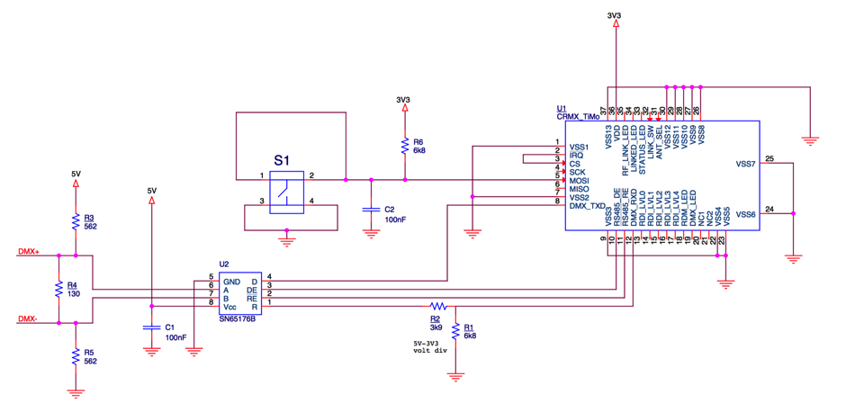 Example using flex mode selection switch