DMX Interface
This chapter explains the two separate DMX interfaces available on the TiMo module.
SPI
DMX data is available to be read over SPI when in receiver mode. This applies to both Null Start Code (NSC) data and Alternate Start Code (ASC) data.
NSC data can be written via SPI in transmitter mode.
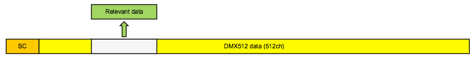
DMX window
The DMX window feature allows a host CPU to set up a span of DMX slots (aka. a DMX window) that the host is interested of. This will reduce the load of the host since it does not need to buffer and parse the entire DMX frame.
Instead the host can get an interrupt request (DMX_CHANGED_IRQ) from TiMo whenever data has changed inside the DMX window.
RX_DMX_IRQ is not affected by the settings of the DMX window.
DMX window functionality is only available in receiver modules and TiMo FX operating in receiver mode.
Reading DMX data over SPI (RX mode)
When reading DMX data over SPI, the longest block of data possible to read is 128 bytes. If it is required to read more than 128 bytes this must be done by performing multiple consecutive READ_DMX command sequences.
The internal data block counter is reset when the end of the DMX window is reached, or if any other command is being sent to the SPI slave.
Writing DMX over SPI (TX mode)
First the correct DMX specification needs to be configured in the DMX_SPEC register, data can then be written using the WRITE_DMX command. Data is written in blocks, no more than 128 slots at a time. To write a full universe of 512 slots four consecutive calls to WRITE_DMX with 128 slots each must be made.
It is possible to write smaller blocks, but not larger than 128 slots.
UART DMX/RDM interface
The UART DMX/RDM interface of the TiMo module consist of 4 digital signals that can be used to interface an RS485 driver IC compliant with the ANSI E1.11 DMX512-A standard to facilitate a DMX512-A compatible interface. Please refer to the example schematic on page 7 for details on how to connect an RS485 driver IC.
The DMX interface can also be used for CMOS/TTL level directly interfacing, for instance to a host CPU.
NOTE: Signal on RXD pin must NOT exceed V~DD~ ! If 5V signal is used, a level shifting circuit must be used. Please see example schematics on page 7 for details on how to use a 5V IC.
DMX and RDM termination and line bias
DMX and RDM termination and line bias circuitry is not provided as part of TiMo (since the data is provided at TTL level). This circuit is left to the device manufacturer to provide as required for each particular application and device.
Termination and line bias circuitry requirements shall follow ”ANSI E1.20 - 2006 / Entertainment Technology-RDM-Remote Device Management over USITT DMX512 Networks” or later revisions.
IMPORTANT: Biasing is mandatory for all RDM implementations.
DMX frame rate and size
TiMo will auto sense the DMX frame rate and frame size and accept all variations that are within the USITT DMX-512 (1986 & 1990) and DMX-512-A standards.
Minimum DMX frame size is 1 slot and maximum is 512 slots.
Minimum DMX frame rate for normal operation is 0.8 frames per second and maximum is 830 frames per second.
Input frame rates below 0.8 frames per second, i.e. more than 1.25s has elapsed since the start of the last frame, will be treated as a loss of DMX. TiMo modules in receiver mode will set the RS485 driver IC to a high-impedance/tri-state mode until another DMX frame is detected. TiMo in transmitter mode will keep the RS485 driver in input mode.
CRMX will propagate DMX through the system maintaining the input frame rate and frame size with the exception of frame rates that exceed those allowed by the DMX 512-A standard.
Input DMX frame rates above 830 frames per second will propagate through the system at 830 frames per second to ensure that the DMX output is compliant with the DMX512-A standard.
DMX start code frames
DMX packets with start codes other than the DMX default 0x00 (also known as the Null Start Code, or NSC) and the RDM start code (0xCC) will be propagated through the system, and are subject to the same rules and limitations as the null start code packets. Such frames are called Alternate Start Code, or ASC, frames.
RDM start code frames
Frames with RDM start code (0xCC) are handled separately by transmitters in CRMX systems, as part of the proxy functionality. Transmitters manage the interleaving of RDM frames with null start code packets across the air, and may interleave other RDM frames that are needed to manage the proxy functionality. This may result in RDM frames can appear on the DMX/RDM interface in a different order than on the input of the transmitter.
All RDM frames are handling in compliance with the PLASA E1.20 standard.
TiMo FX in transmitter nodes discards all frames with RDM start code (0xCC) and RDM draft start code (0xF0).
Alternate start code frames
ASC (Alternate Start Code) frames can be read separately from the SPI interface or the DMX/RDM interface. Over SPI, the ASC_FRAME register contains basic information about the last received ASC frame. The information available in this register is start code and length (number of slots).
Reading ASC data over SPI
When reading ASC data over SPI, the longest block of data possible to read is 128 bytes. If reading more than 128 bytes is required, this is done by performing multiple consecutive READ_ASC command sequences.
The internal data block counter is reset when the end of the ASC frame is reached, or if any other command is being sent to the SPI slave.