Pin assignments
Pin functions
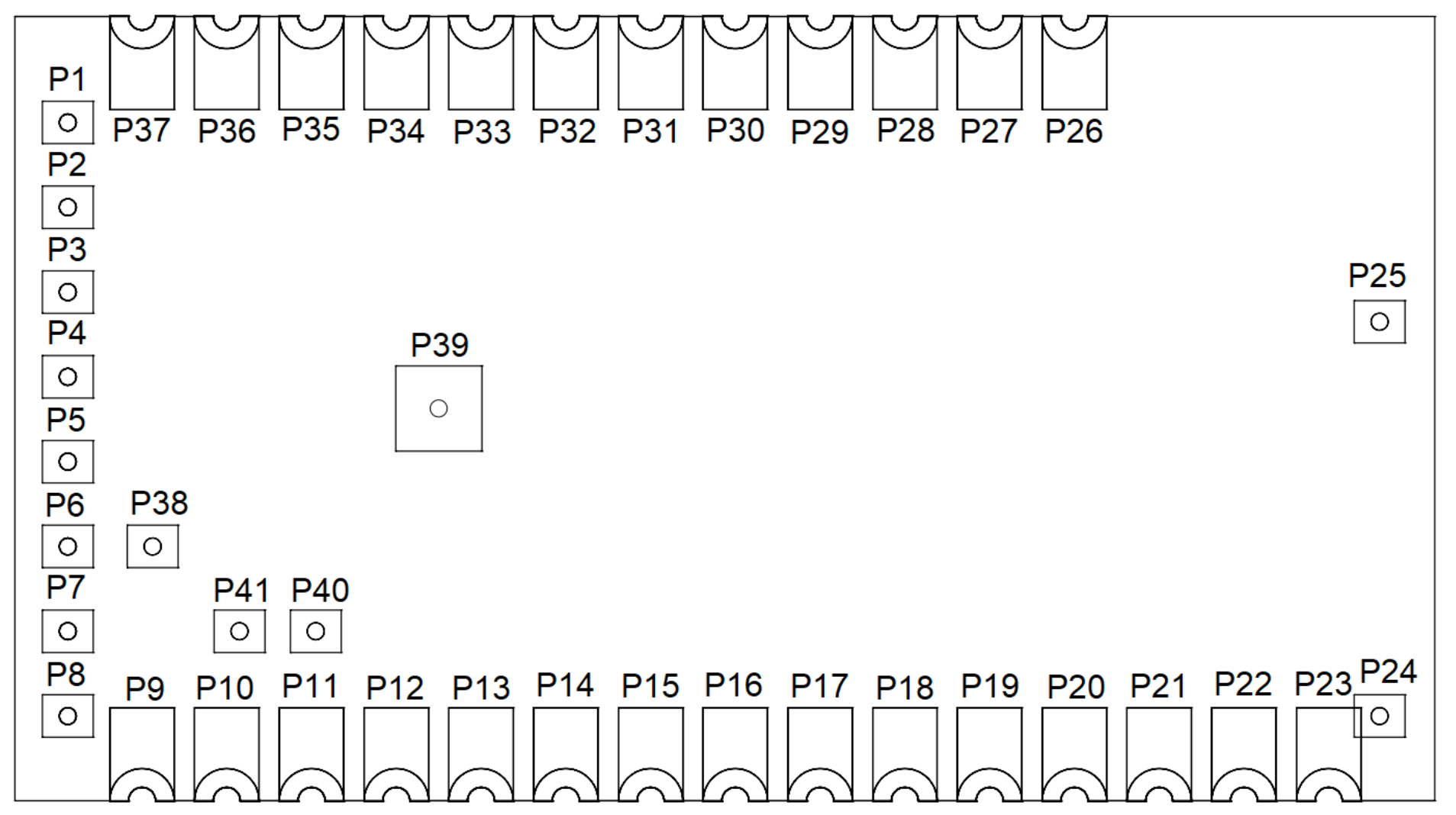
Module seen from top.
| No | Name | Type | Description |
|---|---|---|---|
| P1 | VSS | Power | Ground (0 V) |
| P2-P3 | N.C. | No connection | Do not connect |
| P4 | TxD | UART transmit | Reserved for future use |
| P5 | RxD | UART recieve | Reserved for future use |
| P6 | N.C. | No connection | Do not connect |
| P7 | VSS | Power | Ground (0 V) |
| P8 | N.C. | No connection | Do not connect |
| P9 | VSS | Power | Ground (0 V) |
| P10 | SUBNET | Digital input | High: subnet 2, Low: subnet 1. Internal Pull up |
| P11 | CTRL | Digital input | High: idle, Low: active. Internal Pull up |
| P12-P18 | N.C. | No connection | Do not connect |
| P19 | N.C. | No connection | Do not connect |
| P20 | SWDIO | Serial Wire Debug IO | See pin description below |
| P21 | SWDCLK | Serial Wire Debug CLK | See pin description below |
| P22 | ANT | Antenna selection pin | High: internal, Low: external. Internal Pull up |
| P23-P27 | VSS | Power | Ground (0 V) |
| P28-P30 | N.C. | No connection | Do not connect |
| P31 | DALI RX 2 | DALI recieve pin 2 | Active high |
| P32 | DALI RX 1 | DALI recieve pin 1 | Active high |
| P33 | DALI TX 2 | DALI transmit pin 2 | Active low |
| P34 | DALI TX 1 | DALI transmit pin 1 | Active low |
| P35 | N.C. | No connection | Do not connect |
| P36 | VDD | Power | Supply (3.3 V) |
| P37 | VSS | Power | Ground (0 V) |
| P38 | N.C. | No connection | Do not connect |
| P39 | VSS | Heatsink | Connect to VSS |
| P40-41 | N.C. | No connection | Do not connect |
DALI TX pin description
Pins P33, P34 are both used for transmitting DALI serial data and shall be connected to each other externally. The polarity is active low, similar to the DALI protocol polarity, and thus an external pull up is recommended to avoid undefined behaviour during power off.
An external transistor circuit is needed to sink the required DALI Bus PSU current, see the typical application circuits section for an example.
DALI RX pin description
Pins P31 and P32 are both used for recieving DALI serial data and shall be connected to each other externally. An external pull up is recommended. The polarity is active high, meaning that an active DALI bus (low voltage) shall correspond to high voltage on the input pins. Thus, external polarity flip and voltage shift circuitry is necessary, which can be achieved with only a few components. See the typical application circuits section for an example.
CTRL pin description
The CTRL pin is used for two functions. The first being to trigger a reset to factory default upon release of the pin after being held low for >3s during operation. This will disconnect the module from any mesh network that has been set up. The second function is to put the module in bootloader mode if the pin is held low during power on. This is a reserved mode that shall be avoided but is included here for transparency.
The CTRL pin is active low and has an internal pull up.
| CTRL pin action | Effect |
|---|---|
| 0 V for >3s | Factory reset of W-DALI Node module |
| 0 V during power on | W-DALI Node module enters bootloader mode (reserved) |
Subnet pin description
The subnet pin can be used to select between subnet 1 or 2 for W-DALI network setup with a LumenRadio W-DALI RIN rail gateway without the W-DALI app.
The SUBNET pin has an internal pull up.
| SUBNET pin level | Effect |
|---|---|
| Low | Node module will join gateway set to subnet 1 |
| High or floating | Node module will join gateway set to subnet 2 |
UART pin description
Pins P4 and P5 expose a UART interface to the W-DALI Node module. It is reserved for future use.
ANT pin description
The state of the ANT pin is read during startup of the device. It has an internal pull-up which defaults it to the internal antenna if it is floating. If externally connected to 0 V, the module will instead use the external antenna through the u.FL RF antenna connector. Always keep an antenna connected to the port if operating in external antenna mode. Failure to do so may result in damage of the radio.
SWDIO, SWDCLK pin description
Pins P20, P21 expose the serial wire debug interface of the internal nRF5240 chip. The W-DALI Mesh OEM module comes flashed, licensed and ready to go without programming, but as an OEM integrator it is beneficial to run a custom radio test firmware during system certification according to applicable radio standards. The debug interface can be used to flash the module with test firmware. LumenRadio can provide firmware and guidance for efficient radio certification of the OEM product.
RF antenna connector
The top of the W-DALI Node module features an RF antenna connector of u.FL type which allows the use of an external antenna for improved range.