Mira mesh networks
Mira networks are self-organising, self-healing wireless mesh networks where devices in the network helps forwarding packets to the destination. The network will handle all infrastructure forming by itself, without user intervention. Read more about mesh networking here.
Roles
There are different roles in a Mira network. In this section these roles will be explained.
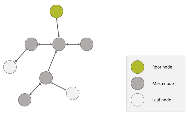
Figure 1: A Mira mesh network.
Root node
A root node is the root of the routing tree (read more about the routing here) and the network is formed around root nodes. The routes in a Mira network are optimised for sending data to and from a root node. A root node is typically used as a gateway or controller unit.
The IPv6 address of the preferred root node (in respect from a given node in the Mira network) can be obtained at any time through the Network API.
Mesh node
A mesh node is a node that helps forwarding data to and from other nodes. They may also be referred to as routing nodes.
Mesh nodes can be addressed using their IPv6 address.
Leaf node
A leaf node is a node that does not offer the ability to route traffic to/from other nodes.
In a Mira network, the sole purpose of leaf nodes is to achieve ultra-low energy consumption, allowing for over 15 years on a AA size battery, while still being able to receive packets being sent to it's IPv6 address.
Performance rates
Mira nodes of all roles supports having different performance rates. This allows for instance having either mesh nodes with high performance running from mains power, or lower performance mesh nodes running from batteries (while possible, it is not recommended to use slower rates than 8 for mesh nodes).
It would also be possible to have leaf nodes with low current consumption and longer response times (when sending data to them) or with better response times and a slightly higher current consumption.
Effectively the performance rate controls how often a particular one node turns on its radio for receiving packets.
Nodes in a network may have different performance rates, which means that it is possible to mix high performance mesh nodes with battery powered mesh nodes of needed. The routing mechanisms will automatically take this into consideration to optimise for the best performance and avoid putting unnecessary load onto battery powered devices.
Please see the specifications page for further details on the available rates.
IPv6
Mira networks are IPv6 based. All nodes have an IPv6 address.
6lowpan
The smallest MTU (maximum transmission unit) that is allowed by IPv6 is 1280 bytes. Since the physical radio link in Mira networks has much smaller payload, Mira uses 6lowpan (IETF RFC4944) for compressing the IPv6 header, and to fragment and reassemble the IPv6 packets if needed.
UDP
UDP (IETF RFC768) is supported by MiraOS for the transmission of datagrams over the IPv6 network.
Details about the API for UDP sockets is found in the section about Network API.
ICMP
MiraOS supports ICMPv6, as defined in IETF RFC4443, and provides APIs for some methods, such as ping.
Border router / gateway
Mira networks can be set up together with a border router as a root node to allow for end-to-end connectivity. The border router can be set up to route packets via the Mira network and another IPv6 compatible network, such as Ethernet or WiFi.
Read more about Mira border router.
Routing
Routing in a Mira network is maintained using the RPL routing protocol (IETF RFC6550) and is optimised for sending packets from the nodes in the network to a root node, and vice versa.
Packets between two arbitrary nodes in the network will be routed via a root node.
The routing is self-healing using a minimum cost algorithm, where the cost is calculated as a function that estimates the number of transmissions needed for a packet to reach its destination. Each hop has a penalty cost, to build in a certain threshold for changing route to a new parent node when there are temporary reductions in link quality on a certain link.
Ranknode = Rankparent + Penaltyhop + ETXparent
This way the network will act as a neural network, which results in a self-healing, self-organising network that minimises the number of hops, while reducing the usage of weak links.
ETX
A central term in Mira networks is ETX, or estimated number of transmissions, which is a metric of the link quality to a given node.
The ETX is a weighted moving average of the number of transmissions needed to get an ACK for a packet being sent to the node (on the link layer).
Example 1
An ETX of 1.1 would mean that for each successful transmission, the packet needs to be sent on average 1.1 times - or the equivalent of a PER of 1.0/1.1 = 9%.
Example 2
An ETX of 2.0 would imply that there needs to be on average two actual transmissions on the link to obtain an ACK. That would be equal to a PER of 1.0/2.0 = 50%.
Cognitive coexistence
MiraOS contains LumenRadio's patented Cognitive coexistence methods to improve reliability by avoiding other wireless traffic in the spectrum. Cognitive coexistence also avoids disturbing other wireless systems.
Cognitive coexistence is a unique feature of Mira networks, that allows your system to communicate both today, and in the future.
Joining a network
When a node starts the network stack, it will automatically start trying to join a network - given that the correct PAN ID and AES keys are provided. Simply put, the joining process goes through a few steps:
- Scanning
- Associated
- Joined
Credentials (PAN ID/AES key)
The PAN ID is a network ID that identifies the network, and the AES key is the encryption key used for the link-layer security.
MiraOS does not store these credentials in any non-volatile memory, it is the responsibility of the application to store these credentials in a safe and secure way.
Choosing PAN ID
The Pan ID shall be a 32-bit value, that meets the following requirements:
- It shall not be the Access Address for BLE advertisements (0x8E89BED6).
- It shall not have a sequence that only differs one bit from any other known PAN ID or BLE advertisement Access Address.
- It shall have a minimum of two transitions in the most significant six bits.
- It shall have no more than six consecutive zeros or ones.
- It shall have no more than 24 transitions.
- It shall not have all four octets equal.
Choosing AES key
The AES key follows the 128-bits Advanced Encryption Standard and can be set to anything that can be considered secure, i.e. an arbitrarily random number.
The join process
Scanning
When the device starts the stack, it will start scanning for the network.
If the node fails to associate with the network within 5 minutes, the node will stop scanning for 30 minutes to preserve battery. Each time the association fails the idle period is doubled, up to the point where the node scans once every 24 hours.
Associated
In the associated state, the node is part of the frequency hopping.
However, it is still not possible for the node to send network traffic (apart from multicast traffic).
Joined
When the routes have been established the node reaches its final, joined, state.
In the joined state it's possible for the node to send and receive unicast packets.